Hello,
thanks for taking the time to read this.
I have kicker kx400.1 amplifier. And it is in protection mode, sort of. Red protection mode led blinks alternately with green led. There is no visible damage on the board.
So i need help to find out what is wrong with it.
Leds blinks with the same frequency as voltage changes on TL494 pins 9 and 10 slowly from zero to 5 volts(square wave). And nothing happens.
When i take off smaller board where input signal goes in and out ( there could be oscilator on it. there are two ICs with text scrached off) and turn on amplifier, protection led dont light up and green LED lights. Voltage on TL494 pins 9 and 10 raises to 10 volts and relay is triggered (close the circuit).
Could problem be on that smaller board with two unknown ICs?
Do you have have a multimeter?
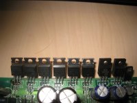
Disconnect power to the amp and let the amp sit for 10 minutes, so that any residual charge on the filter capacitors drain off . Check the outputs FET's with an ohmmeter. Write your results as follows:
Left to right:
Pin 1 to Pin 2
Pin 1 to Pin 3
Pin 2 to Pin 3
You should have a high resistance all around.
The KX400.1 has two IRF640's and four IRF9640's. It is common for the IRF640's to short. I believe this is correct but it's been awhile since I've worked on one off these amps.
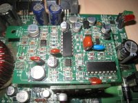
The smaller board is the class D circuit and is also prone to failure and may need to have one or two IC's replaced.But don't worry about that until you know whether the outputs are shorted!
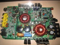
Please post pictures of the board when you can, one of the whole board and a close up of outputs and class D board.
Disconnect power to the amp and let the amp sit for 10 minutes, so that any residual charge on the filter capacitors drain off . Check the outputs FET's with an ohmmeter. Write your results as follows:
Left to right:
Pin 1 to Pin 2
Pin 1 to Pin 3
Pin 2 to Pin 3
You should have a high resistance all around.
The KX400.1 has two IRF640's and four IRF9640's. It is common for the IRF640's to short. I believe this is correct but it's been awhile since I've worked on one off these amps.
The smaller board is the class D circuit and is also prone to failure and may need to have one or two IC's replaced.But don't worry about that until you know whether the outputs are shorted!
Please post pictures of the board when you can, one of the whole board and a close up of outputs and class D board.
Last edited:
U908 is a weak link on that driver board (PAS204-31?).
Do not remove or install that driver board while the capacitors are charged or while the amp is on. Make sure that it's fully inserted in the connectors at all times. Failure to do so could cause the output transistors to fail.
In most of the amps that use this type of circuit (Kicker, Orion... the IRFB31N20D (purchased from a reputable distributor, not eBay) is a better sub if the 640s need to be replaced - likely OK here but need to be checked as suggested).
Hi,
Here is results of output FETs resistance
Pin 1 to Pin 2 - slowly rising from 50k
Pin 1 to Pin 3 - 49,7k
Pin 2 to Pin 3 - 1k and slowly rising to 4k ohms
Seems to be OK, cause all 6 of them shows the same resistance.
And about U908. It is located on Your mentioned PAS204-31. Could that be the faulty one? Unfortunatelly I cant tell what kind of IC it is, cause text is scrached off.
When I took off PAS204-31 board of main board and powered up with out load and input, protection led didnt light up.
But with that board attached, voltage was oscilating.
Attachments
It's an LM361. It commonly fails but you need to confirm that you have all marked supply voltages on the driver board.
If the voltages on the driver board are relatively steady, posting the DC voltage on all pins of that IC could help determine if it's the culprit.
If you attempt to get the voltage readings, constantly monitor the temperature of all of the heatsink mounted devices to make sure that none overheat.
If the voltages on the driver board are relatively steady, posting the DC voltage on all pins of that IC could help determine if it's the culprit.
If you attempt to get the voltage readings, constantly monitor the temperature of all of the heatsink mounted devices to make sure that none overheat.
Download the JBL BP600.1 service manual from the following site. The output stage circuit should be close to what you have.
ElektroTanya | Service manuals and repair tips for electronics experts
ElektroTanya | Service manuals and repair tips for electronics experts
I took a look at the JBL BP600.1 output stage schematics and as Perry stated are close enough.
Take another picture on the opposite side of amp board. The KX400.1 and/or the KX500.1 had a modification added to the opposite side for the SMPS (small power supply). You will see a couple of surface mount resistors and zener diodes if I'm right, which tend to get pretty warm and may need to be be replaced and solder re flowed.As I stated in a prior post I will consult with my schematics and dig out a junk board if I can find one, Monday.
Take another picture on the opposite side of amp board. The KX400.1 and/or the KX500.1 had a modification added to the opposite side for the SMPS (small power supply). You will see a couple of surface mount resistors and zener diodes if I'm right, which tend to get pretty warm and may need to be be replaced and solder re flowed.As I stated in a prior post I will consult with my schematics and dig out a junk board if I can find one, Monday.
I have measured voltage on LM361
pin 1-11V
2 - 0v
3 - 9Vpp (+3,5; -4,5)
4 - +7; -3,2; 11Vpp
5 - 0V
6 - +2,8; -6,5V
7 - 0V
8 - +6,4; -1V
9 - +5V
10 - +4,5; -2,3V
11 - +6; -1,9V
12 - 0V
13 - +6V
14 - +6V
And on TL494
pin 1-0V
2 - 5v
3 - 0V
4 - 5V
5 - 2,8V
6 - 3,7V
7 - 0V
8 - 5V
9 - 5V
10 - 5V
11 - 11,5V
12 - 14,7V
13 - 5V
14 - 5V
15 - 5V
16 -0V
On LM361 voltage was constantly changing, and it was quite difficult to determine real value of voltage.
All measurements were done without input and load ( if that changes something).
If black probe on speaker negative terminal, than it shows little different voltage values, but still quite changing.
LM361
pin 1 6V
2 0v
3 -5V
4 -2,5 +1,5
5 0V
6 -7V
7 0V
8 1,28V
9 0,5Vpp
10 -1,9V
11 -2,1V
12 0V
13 2V
14 1,4V 1,9Vpp
Could you please tell me, which voltage needs to be read? Vrms, Vmax/min or Vpp
And it is strange, cause voltage waveform is quite undetermined and unclear
LM361
pin 1 6V
2 0v
3 -5V
4 -2,5 +1,5
5 0V
6 -7V
7 0V
8 1,28V
9 0,5Vpp
10 -1,9V
11 -2,1V
12 0V
13 2V
14 1,4V 1,9Vpp
Could you please tell me, which voltage needs to be read? Vrms, Vmax/min or Vpp
And it is strange, cause voltage waveform is quite undetermined and unclear
remove power from amp, let amp discharge maybe 10 minutes. remove PAS204 board, remove solder bridge from pin 3 for now.
Find D4 (this is a 1N4148 diode) and lift one side up so that it is disconnected from circuit, this will disable protection. Return PAS204 board and power up, you should be able to check the voltages.
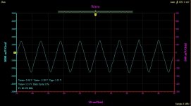
Use your mutimeter for the DC voltages and your scope to look at U908 (LM361) Pin 4 (triangle waveform) and Pin 11(squarewave with 50% duty cycle). As Perry instructed black probeand scope ground on negative speaker terminals.
If at all possible take pictures of waveforms, otherwise discribe waveforms as best you can.
Find D4 (this is a 1N4148 diode) and lift one side up so that it is disconnected from circuit, this will disable protection. Return PAS204 board and power up, you should be able to check the voltages.
Use your mutimeter for the DC voltages and your scope to look at U908 (LM361) Pin 4 (triangle waveform) and Pin 11(squarewave with 50% duty cycle). As Perry instructed black probeand scope ground on negative speaker terminals.
If at all possible take pictures of waveforms, otherwise discribe waveforms as best you can.
Last edited:
When D4 is removed, voltages can be measured easily.
LM361
pin 1: 11.9V
2: 0v
3: -6.8V
4: -0.2V
5: 0V
6: -11.9V
7:0V
8: 2.8V
9: 1.65Vpp
10: -1,9V
11: -1.73V
12: 0V
13: 2.84V
14: 2.84V
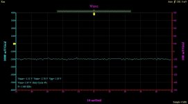
Waveform on Pin4 is nice triange shape, but on pin11 there is nothing close square wave. On output pin 11 it is more like flat line with distortions.
Later I will add pictures.
So, if output of lm361 is not right, than it could cause all that trouble to amp? Or need to check something else?
Before I disconected D4, voltage on +12 and -12 rail was oscilating too. And i started to think that something is wrong with power suppy side.
LM361
pin 1: 11.9V
2: 0v
3: -6.8V
4: -0.2V
5: 0V
6: -11.9V
7:0V
8: 2.8V
9: 1.65Vpp
10: -1,9V
11: -1.73V
12: 0V
13: 2.84V
14: 2.84V
Waveform on Pin4 is nice triange shape, but on pin11 there is nothing close square wave. On output pin 11 it is more like flat line with distortions.
Later I will add pictures.
So, if output of lm361 is not right, than it could cause all that trouble to amp? Or need to check something else?
Before I disconected D4, voltage on +12 and -12 rail was oscilating too. And i started to think that something is wrong with power suppy side.
Since PapaZBill has a schematic, I'll let him guide you on this.
The LM361 has 2 sections. The side of the IC with the ±11v operates much like common op-amps and comparators and can operate from higher voltage supplies than the other side of the IC. The other side operates at lower voltages (commonly associated with digital circuits, 5v is the max supply it will generally have -- sometimes +3 and -2v, other times 5v and ground).
Pins 3 and 4 are the comparator inputs. The square wave output on the 'digital' side is determined by those inputs. The triangle waveform has a fixed amplitude. The instantaneous output of the square wave (pin 9 or 11) is high when the input (on pin 3) is above the instantaneous voltage of the triangle waveform and the square wave is low when the input is below the instantaneous voltage of the triangle waveform. The output of pins 9 and 11 are 180 degrees out of phase (one high while the other is low - differential comparator).
If the input on pin 3 is straight DC and above or below the top/bottom of the triangle waveform, the output on pins 9 and 11 will be straight DC. One will be very near the +3 and the other will be very near the -2v supply voltage.
Pin 11 is used to drive the driver stage for the outputs. When it's near 3v, it drives the high-side FETs on. When it's near -2v, the low side FETs are driven on.
replace the solder bridge to Pin's 1 and 2 of U907-TLO72.
Check for a squarewave on U908-LM361-Pin 11, also Pin 9 is not connected, but should have a squarewave as well.
If you don't have a squarewave, replace U908.
If you do have a squarewave U908 is good and U907 is suspect. If changing U907 doesn't fix the problem, there is something deeper in the circuit, that will require further steps, which I will get into after you posts the results of the current steps.
- Status
- This old topic is closed. If you want to reopen this topic, contact a moderator using the "Report Post" button.
- Home
- General Interest
- Car Audio
- kicker kx400.1 issues