Thanks friends,
You have at least solved my nagging suspicion that the innards of my KA-1500 (that's what it says on the front panel!) do not correspond with that amplifier's schematic. I will now carefully switch it on (test bulb included) to see which parts are working or not. Regards, Joe
You have at least solved my nagging suspicion that the innards of my KA-1500 (that's what it says on the front panel!) do not correspond with that amplifier's schematic. I will now carefully switch it on (test bulb included) to see which parts are working or not. Regards, Joe
To my surprise, considering the state of the unit, with the bulb tester in place, I switched it on and the bulb flashes and dims to flicker, indicating that there are no series problems with the amplifier. However, connecting a pair of headphones to the AUX input, which is the only one connected to the board, doesn't produce any sound.
I suppose that without knowing which pcb is installed in the amplifier case, and therefore without the corresponding circuit diagram, it is going to be very difficult (next to impossible?) to continue working on it.
I suppose that without knowing which pcb is installed in the amplifier case, and therefore without the corresponding circuit diagram, it is going to be very difficult (next to impossible?) to continue working on it.
I suppose that without knowing which pcb is installed in the amplifier case, and therefore without the corresponding circuit diagram, it is going to be very difficult (next to impossible?) to continue working on it.
Well that depends on your experience... you could "busk" this one without any circuit info really.
Basic checks.
1. Have the output transistors got supply.
2. Identify type of output configuration... almost certainly emitter follower.
3. Is the output voltage at zero volts DC.
4. Is the output stage drawing current... easy to check via volt drop across emitter resistors.
When all that is OK you are 90% of the way there.
Thanks guys for your interest and help. Mooly I didn;t have time today to make a systematic check of the points you suggested but when I last switched it on (yesterday?) the was definitely dc on the output transistors. It was 32.5 volts (with the test bulb in place).
Sakis, thanks for your offer. I will email you with a photo of the front panel. However, if bigjim is correct (i.e. the pcb is definitely not that of a KA-1500 MkII and neither of the standard KA1500 from what I've checked) I doubt whether it will match any KA1500 schematic.
I firmly suspect that someone tried to fit another model pcb (possibly not even a Kenwood) into a 1500 enclosure and controls. That's why it looks so untidy (I mean the wires) and with some wires not connected.
Sometimes I wonder whether I should clean up the enclosure and mount some of the equipment I have (a TK2050 Class T amp and SMPS + a D. Self phono preamp) in the KA1500 enclosure, which I find very attractive. The multi-turn stepped 100K volume control has a 'luxury' feel! ...
What are your views?
JA
Hello Sakis and friends - here I am again with a couple of photos as suggested by Sakis. I hope these are of some help to identify the mystery circuit! 
Attachments

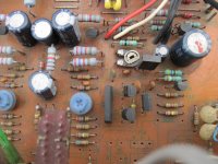
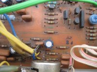
OK THEN ...you are correct the schematics available in the internet do not fit o the picture you are posting there is got to be something wrong still the problem is that construction looks very original
could you please summarize the trouble you are having with it ?
could you please summarize the trouble you are having with it ?
Last edited:
The more you look at the earlier pictures the more you can see it appears to be cobbled together. Look at the (original) small PCB with the switches on. That will be the style of PCB that should be seen with the white printing. Some of the wiring looks of modern type like the soft multicore (flat type) cabling.
Very strange... think I would be tempted to strip it completely and use the case for something else.
Very strange... think I would be tempted to strip it completely and use the case for something else.
I recently bought a KA 1500 for pennies with similar problem....no output at all...
So I make the classic checks and everything was fine! I tear it up and found some cold solders and 2 broken traces.When I power it up the old buddy worked fine! So I change all caps and some resistors,and sounds like a dream!
And some pics:
tearing up...
And the happy time of checking...all transistors are OK and original!!
pre-check...
reassembly...
...and like new! Ready for another 40 years...
So I make the classic checks and everything was fine! I tear it up and found some cold solders and 2 broken traces.When I power it up the old buddy worked fine! So I change all caps and some resistors,and sounds like a dream!
And some pics:
tearing up...
An externally hosted image should be here but it was not working when we last tested it.
And the happy time of checking...all transistors are OK and original!!
An externally hosted image should be here but it was not working when we last tested it.
pre-check...
An externally hosted image should be here but it was not working when we last tested it.
reassembly...
An externally hosted image should be here but it was not working when we last tested it.
...and like new! Ready for another 40 years...
An externally hosted image should be here but it was not working when we last tested it.
- Status
- This old topic is closed. If you want to reopen this topic, contact a moderator using the "Report Post" button.
- Home
- Amplifiers
- Solid State
- Kenwood KA-1500 transistor fault?