I just got a Valhalla ohm meter (measures <200m to 10.9k ohms).
http://www.testequipmentconnection.com/specs/VALHALLA_4100ATC.PDF
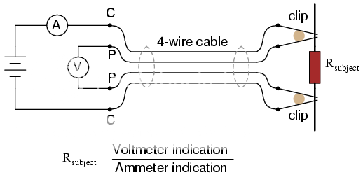
There are Kelvin connections ....4 banana/binding posts....2 for voltage(hi/low), 2 for current (hi/low).
When making my own cables, using 2 coax cables, should "current wires be the shield and "voltage" be the inner wire?....or the other way around?
Unlike the picture, I'm not using 4 wire cable, I'm using a pair of regular coax.
I do have some triax cable somewhere, if adding an extra grounded shield is better.
=RR=
http://www.testequipmentconnection.com/specs/VALHALLA_4100ATC.PDF
There are Kelvin connections ....4 banana/binding posts....2 for voltage(hi/low), 2 for current (hi/low).
When making my own cables, using 2 coax cables, should "current wires be the shield and "voltage" be the inner wire?....or the other way around?
Unlike the picture, I'm not using 4 wire cable, I'm using a pair of regular coax.
I do have some triax cable somewhere, if adding an extra grounded shield is better.
=RR=
BTW....searching the net...here might be a DIY low-ohm measuring project for the the inner-nerd inside you.
Although I don't know what the best 1k freq source might be.....
http://www.analog.com/static/imported-files/application_notes/22192533AN306.pdf
The equation for resistance is :
R= 0.0157 x Vout
(0.0157 = 15.7mV)
...I wonder is a DC volt panel meter could be implemented to calculate the equation, to display the actual ohms...??
=FB=
The Kelvin connection is to eliminate the volt drop due to the current flowing in the test leads affecting the voltage measurement. The voltmeter is high impedance and so no current flows in these leads. The voltage at the meter is thus the same as the voltage across the resistor under test.
As the voltmeter is high impedance I would use a shielded cable for the voltage measurement and a second cable for the current so that the current doesn't inductively couple into the voltage reading.
If you have a good constant current source then a DPM can be calibrated to read ohms directly over a limited range. Switching the current will extend the range.
- Status
- This old topic is closed. If you want to reopen this topic, contact a moderator using the "Report Post" button.