Nice one. I used to live to Leicester for over 8 years, and used to visit Wilmslow Audio almost every other month, This is the the 3rd pair of KEF 104aB i am preserving. Let's see how it goes.
I know the limitations of the KEF104 and LS/35a. Music is a very subjective matter.
I know the limitations of the KEF104 and LS/35a. Music is a very subjective matter.
Very interesting interview with Alan Shaw of Harbeth. Well, I found it interesting.
YouTube
Damped MDF boxes, these days. His plastic radial cone is really very interesting. Very rigid! Not like the old polycones I remember at all!
Metal tweeters as well. I think he must be doing interesting things in his crossovers. Difficult impedance, as it goes. I think I worked out he uses 15dB slope on his woofers, being observant. But always based on comparing to live sound.
I love my 104abs. My first real speakers bought from a gent in Dartford who had them from new but change in decor meant he was required to buy new kit. I first fell in love with them at a used hifi place around the corner from me (now sadly gone) as the owner used a pair to demo his stock (unless of course you were buying speakers!). It took me a few years to find a pair that I was happy with that were also close enough to fetch to my place.
Hadn’t seen this thread before. Will have to pull my crossovers out and have a look at what I did a couple of years ago when I replaced crossover with kit from Wilmslow Audio.
Hadn’t seen this thread before. Will have to pull my crossovers out and have a look at what I did a couple of years ago when I replaced crossover with kit from Wilmslow Audio.
Clearly sthcoaster, you didn't check out the modern (Harbeth) take on polycone 8" bass plus 3/4" tweeter. I can tell because you posted so fast.
You can love your KEF 104ab, which is essentially a two way with an ABR, but what does it all mean?
I like retro myself. Many a £30 bargain to be had in the junk shops these days.
This is one of the better old paper bass Wharfedale speakers. The Wharfedale Shelton XP2.
My surprise was total with the crossover. It was SO KEF! But maybe not KEF 104ab.
Why does this cheapie speaker sound so good? Because I have heard a few. And any fool can get frequency response accurate.
I think 3/4" mylar domes like the KEF T27 have a good sound. But it's actually in what the drivers see from the amp. A low (damping of voicecoil) impedance. This changed my way of looking at crossovers. It is measureable.
Hiya mate, nice pics of the Cresta and Chorale. They were using the older versions drivers. Cresta was using the 60s tweeters. The T27 SP1032 appeared in the 70s. The B200 has a few versions. SP1063 (smaller magnet) and SP1039 (bigger magnet short coil).
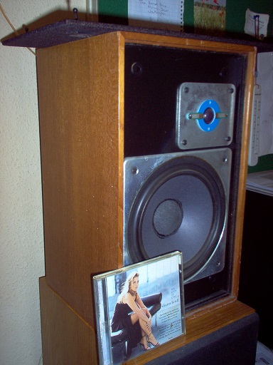
Owners of KEF104aB had issues with burned T27, and the deformation of cone surround on the B200 (voice coil rubbing). Never mind the state of the cross overs, many KEF 104aB need restoration or repair work by now. These are near 50 years old speakers. Restoration work was difficult for a long while because of parts availability. The good news is in recent years Ebay started to offer aftermarket T27 voice coils, ferro fluid and rubber surround for B200 replacement/repair work. In Singapore, there is a specialist speaker repair shop 'Martin Electronics'. They have been repairing KEF speakers since the 70s.
By repairing the KEF 104aB I can bring it back to how it should sound. KEF104aB was famous in playing back classical chamber music. I have compared two working pairs of KEF 104aB and they both sounded very different. Measurements of the basic parts like RLC were about the same. Maybe it has to do with the state of the individual drivers.
The German speaker company Monacor offers drivers that can replace the old KEF B110 and B200. The Monacor SPH135 and SPM205 have been used to restore some old LS3/5a and KEF 104. Performance wise, they are far better than the older B110 or B200. (and you can say it is NOT KEF sound)
I have modified a KEF 104 into a KEF 104aB taming the nasty behavior of the T27. The cross over schematics you listed has a few interesting modifications that was not on the original cross over board:
1. Zobel net work added for both tweeters and drivers
2. Attenuation of the tweeter
I am changing the 104 into Active + Bi-amp. By doing so I can vary the individual driver cross over Fc @3khz + sensitivity. The system can be adjusted based on Subjective listening and/or near field measurement. I can use a good pair of KEF 104aB with passive cross over as baseline. This adds a lot of fun in integrating the drivers as well as understanding the driver characteristics.
I have a concurrent on going project to remake a KEF 105.2 (used to own a pair in the 80s). The design basics are referenced, and using modern drivers : Peerless 12in, Monacor 5in and the Morel MDT30. No more 70s passive crossovers. it will be LW 3 band active cross overs and tri-amped.
I know. Time flies. I have been here for 10 years now.
KEF were the great innovators in plastic coned loudspeakers. A tradition that is still alive and well if you follow Harbeth, Spendor, Stirling Broadcast and the like. KEF's designs mostly were derivatives of the two classic combinations below. 8" and 5" bextrene bass, 3/4" plastic tweeter.
For those who don't know much about this BBC derived style here's a fine modern Harbeth Super HL5: Harbeth Super HL5plus loudspeaker | Stereophile.com
There's no "boom and tizz" in this style. It's all about realistic reproduction of classical music and voices. Accurate monitors.
KEF were also extremely competent at crossovers for badly behaved drivers. And the old ones WERE pretty awful.
I think you'll find, Jon, that a lot of KEF designs were a very deliberate BW3. This is a good idea, IMO. There actually isn't a +3dB bump at crossover because the phase is 90 degrees. Which helps dispersion and flattens power response in 3 out of 4 directions.
You can always add an order to both arms of the crossover and get LR4. But that is a different sound. For sure, there is a lot to learn from KEF crossovers. They all have something going for them. Which is why people still revere the KEF built 11 ohm BBC LS3/5A and your KEF 104ab.
Today is July 2018. I have another KEF cabinet restored with real wood veneer and also improved on the cabinet integrity.
1. The original chipboard was of very poor quality. I have to apply a few layers of wood lacquer internally to hold everything together. The speaker mounting areas were strengthened with braces.
2. B200 repaired with the voice coil realigned and surround replaced.
3. Passive crossover checked (as a backup since the speaker will have active cross over)
I have the option to configure the cross over as a 3rd order Butterworth at 3khz, of LR 4 at 3khz.
To be continued.
I know. Time flies. I have been here for 10 years now.
KEF were the great innovators in plastic coned loudspeakers. A tradition that is still alive and well if you follow Harbeth, Spendor, Stirling Broadcast and the like. KEF's designs mostly were derivatives of the two classic combinations below. 8" and 5" bextrene bass, 3/4" plastic tweeter.
For those who don't know much about this BBC derived style here's a fine modern Harbeth Super HL5: Harbeth Super HL5plus loudspeaker | Stereophile.com
There's no "boom and tizz" in this style. It's all about realistic reproduction of classical music and voices. Accurate monitors.
KEF were also extremely competent at crossovers for badly behaved drivers. And the old ones WERE pretty awful.
I think you'll find, Jon, that a lot of KEF designs were a very deliberate BW3. This is a good idea, IMO. There actually isn't a +3dB bump at crossover because the phase is 90 degrees. Which helps dispersion and flattens power response in 3 out of 4 directions.
You can always add an order to both arms of the crossover and get LR4. But that is a different sound. For sure, there is a lot to learn from KEF crossovers. They all have something going for them. Which is why people still revere the KEF built 11 ohm BBC LS3/5A and your KEF 104ab.
What is the crossover schematic in your post?
Is it a KEF design or your own?
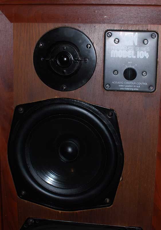
@nimo_jon To the OP, how was the contour switch implemented in the original 104aB?
I see that your simulation schematic for the aB includes the parts upgrades that you did.
Hi, sorry for the late reply. You can find the inductor values here:
403 Forbidden
Basically it is shifting the low pass frequency LC filter to get the contour. I stick to the neutral setting.
Nimo_jon, would you have any tips for realigning the b200 voicecoil? I have a rubbing b200 in a KEF104 which I would like to get working again, but am nervous about wrecking it! Thanks..
You need to get a replace rubber surround (search Ebay seller from China on 8 in rubber surround). The reason the coil is rubbing is due to the distorted surround pulled the coil to one side.
1pcs 8"inch Speaker rubber Edge Speaker surround repair DIY 178C/K11/K12/178A | eBay
With the surround removed the coil should be centralized. If not, the spider could be gone too. Usually the spider is fine.
Reattach the surround with proper glue and clamps. This should fix it.
You can contact Martin Electronics in Singapore, they are pretty good at it.
I am a new member trying to restore a pair of Kef 104ab. They seem in great condition but given the age time may have taken its toll on the electronics etc. They currently sound very boomy and muddled in the midrange. Perhaps my listening room is too small (4.5m by 5m). I can't quite follow all the technical talk as my understanding of electrical circuits and how components interact in crossovers is basic. Great information here and many thanks to all that have contributed. I really want to have a go at building nimo_jon's replacement crossover. Maybe a bit ambitious for my first DIY speaker project. Do I need to do something to be able to see the 104ab schematic properly? Perhaps someone could advise.
Recently, I bought a set of 104 non-aBs for 50 Euro with water-damaged enclosures.
Since these are the 5th 104 pair I own, I decided to use this set for experimentation. I took out the drivers and the crossovers, and wired each B200-T27 pair to the speaker outputs of an IKEA Symfonisk. To be safe on the T27s, I soldered 500mA fuses in series, just as in the 104aB crossovers.
First without any enclosure in Linkwitz configuration (B200s pointing upwards). I was quite surprised about the output of this set! Off course, there was a lot of cross-talk due to the acoustic short circuit of front and back waves of the B200s. Obviously, there was hardly any normal bass, but its phantom was perceivable.
Today, I put the B200s in 1mx20cm diameter drain tubes, which fully resurrected the bass, maybe a bit too much and too boomy. As the T27s were not fully centered above the B200s, there was some combing interference. Possibly the T27s were also driven too low down (i.e. below 2800 Hz) resulting in some distortion. Some damping helped the roominess, all of course after the Sonos TruePlay in the app.
I decided to resurrect the non-104aB crossovers, but they now need conversion to bi-amping, since this is what the Symfonisk delivers. I will give it a try tomorrow.
If this would work? Not a bad deal: 50 Euro of electronics (written-off 104s), 100 Euro of drainpipe materials, 200 Euro of Symfonisk speakers as amps, for a 350 Euro and almost hifi streamable set of active speakers... I will keep you posted!
I just recapped a rather nice set of ABs the original grills are even perfect. The cabs needed work inside the driver brace was not even touching the speaker and a lot of glue issues. I 1/4 rounded all seams and also did a few other tricks. They sould very good right now and have no foam in them at all. I sprayed the insides with Boom Mat, glad it worked lol.
I would love to make crossovers like yours but I don't have the expertise and I realize that you have done some research and some effort to complete this great job. I have read your post carefully but, as far as I can understand, I have not been able to come up with a "shopping list" or a real scheme. Can you / will you help me, please?The vintage KEF104 series loud speakers still command a lot of respect today despite its age and simplicity in design. They have been many music lovers’ favorite speakers, and will continue to be much loved.
These 70s speakers have come of age and parts are no longer supported by KEF. If the speakers have spent time in humid conditions, it would require a complete overhaul for sure, after 30years in service. The crossover needs to be checked for component accuracy. And the drivers need to be checked for the correct mechanical and electrical properties.
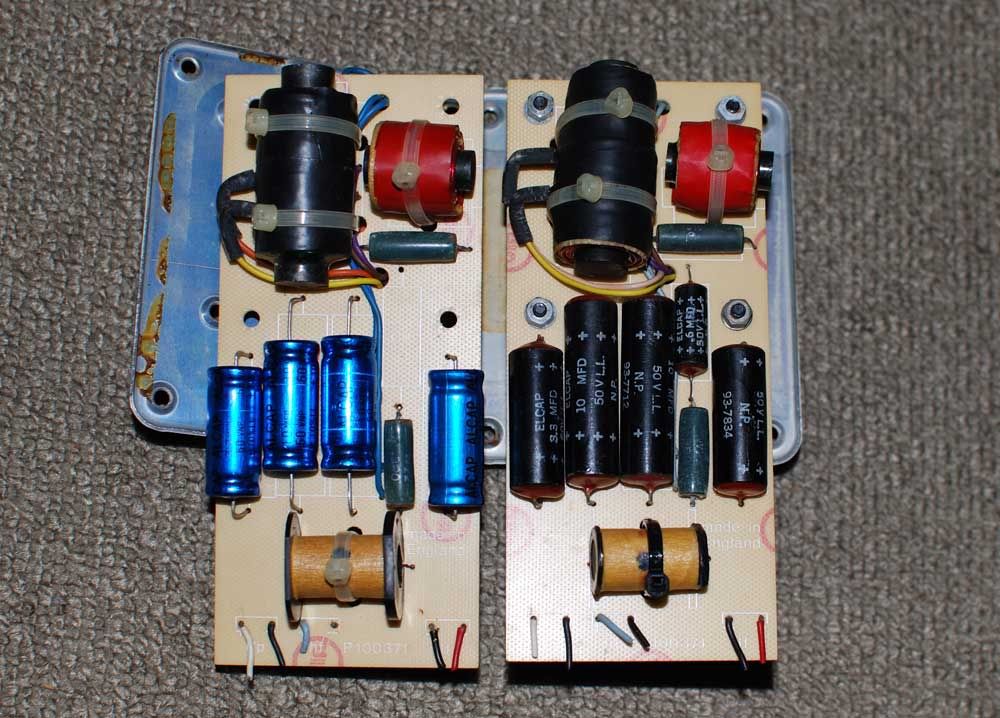
The crossover’s circuit board traces will have oxidation and corrosion after years of services. On close inspection and measurement, cross over tracks may have become thinner and pose a much higher series resistance in its path. In some cases, the corrosion may have introduced an open circuit.
The old black Elcap black capacitors on the cross over will have to go, even if kept from new. I have measured many of such capacitors. Even good meters usually could not determine the component’s correct values (not less, but strangely, much larger capacitance).
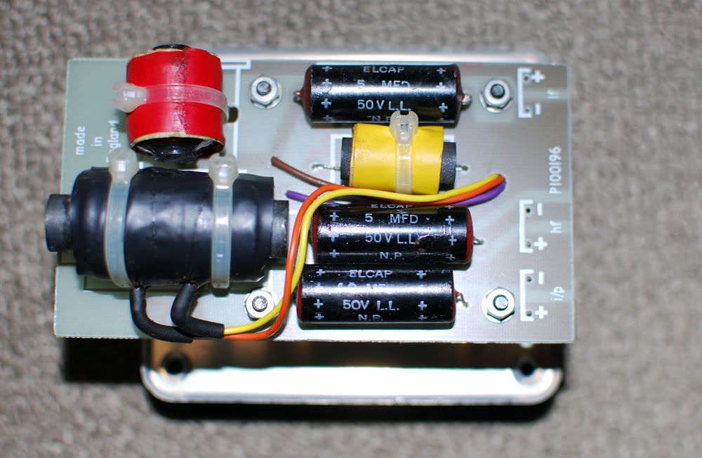
The old Alcap caps may still retain its value after 20 years. Modern capacitors can perform much better. There has been discussion on the series resistances of the cap that affects cross over design. There appear to be two schools of thoughts, and both have their merits.
The simple, small ferrite coils may suffer from hysteresis. At high currents, or fast changing frequencies, any ferrite core will saturate magnetically and cause a non linear departure from the ideal behavior. This will manifest as distortion. The crossovers are placed very close to the driver units (behind the metal plates). Although there could be no significant magnetic coupling path, inductors are best free from strong magnetic fields. (The selector on the KEF face plate introduce contact resistances.)
The internal wiring of these speakers is thin, and made of a few tinned cores. The fact that the crossover sits at the top right of the speaker, to facilitate selection of frequency responses, require a longer wire run. This adds to the current limiting effect of the internal wiring.
As such, the original crossover is best left as is, and a new cross over based on the old design be constructed as replacement. KEF did not put together a speaker crossover from a pile of loose parts. Individual parts must have been measured, put together, and then measured again, to meet a tight specification.
Therefore, to rebuild a crossover, we must at least have a RLC meter, SPICE software to determine the correct modern equivalent for replacement. We need to understand why the crossover was designed that way, and a measurement tool to meet that specification or goal.
Having said that, we may never be able to determine the original design goals KEF had. But KEF certainly had a design budget and there always will be a spread in specification during mass production. This is not building a pair of speakers from scratch, and we can get away from using an expensive full range SPL measuring device.
ORCAD SPICE SIMULATION
This is the original KEF 104 equivalent circuit in SPICE based on KEF’s published driver data sheets. Note that for the passive components during simulation, the inductor is always made up of an inductance and a series resistance (determined by measurements). Inductors have stray capacitance but ignored. Capacitance will have series resistance but ignored. Resistors will have series inductances, but small enough to be ignored.
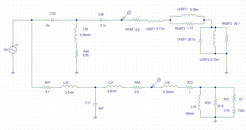
As the simulation is based on the equivalent circuit, this is only an approximation of the actual voltages appearing at the driver’s terminals. This is NOT the actual SPL output of the driver as the driver has its own non linear responses. The simulation studies the electrical characteristics in the frequency domain.
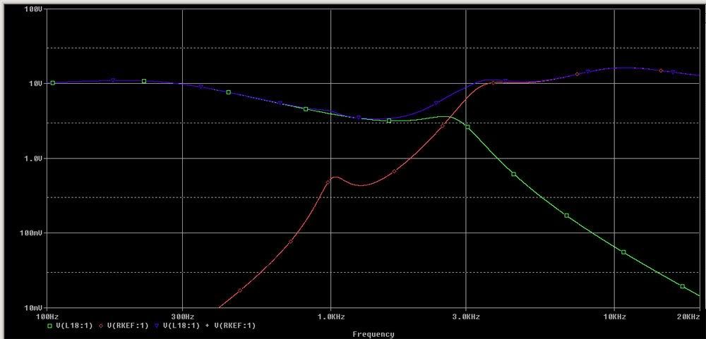
The red trace shows the voltage appearing on the T27 tweeter terminals, and the green trace the voltage appearing at the B200 bass driver terminals. The blue trace shows the summed voltage on the two drivers.
The red trace shows that there is no treatment of the natural resonance at 1.1khz for the T27A driver. There is a very slight hump at the 1kHz summed output (log scale) due to this 'resonance'. This is certainly undesirable.
The green trace shows a kink at the 2.5khz region for the bass driver.
The summed output shows that from 2.5kHz to 3kHz the transition is not smooth. However, the measured SPL of the drivers may be flat (as shown by KEF) due to the non linearity of the drivers.
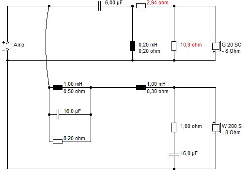
This is the KEF 104aB crossover.
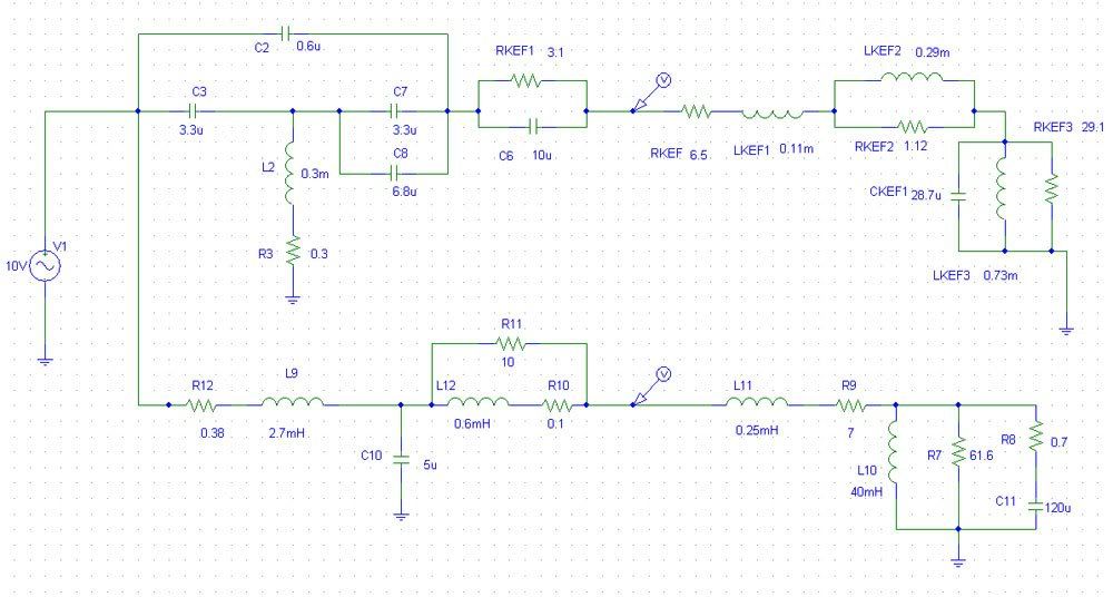
The introduction of a 0.6uf MKT type cap at the high pass, will result in a snubbing effect at the 1.1khz region, thereby attenuates the natural resonances of the T27 driver. The T27 will start to exhibit a falling SPL above the 10khz region, so the introduction of a paralleled 10uf with 3R combo will boost the output above 10khz, and flatten the resultant measured SPL.
As modern caps have lower series resistance (low ESR), this can be compensated by a very small series R, so 3R in the high pass section can be selected to measure 3.1R or 3.2R to retain that damping effect. The value printed on the component may not be the actual value of the component.
The 0.3m inductor is realized by an air cored inductor with only 0.3R dc. The original ferrite core measured 0.55R dc. The resistance of the inductor determines how deep the attenuation of the 1.1khz notch would go. At 0R the attenuation will be close to full attenuation, ie, a short circuit. However, in a real component, there is always some resistance present. It is good to use MKT type for the 0.6uf cap that has a certain series resistance.
The choice of series inductance 2.7mH needs a low series resistance and low magnetic hysteresis. Ideally, an air cored inductor will have the least distortion as there is no core saturation. However, it is hard to find one air core inductor that gives 2.7mH and lower than 0.5R in resistance. The Mundorff Alconit or ferrite series offers a coil at 0.38R with much lower distortion at high current (high current wire).
The 0.6mH is bypassed by a 10R resistor. An air core unit with 0.1R is good choice.
The simulation of the 104aB voltages with consideration of parasitic properties of the components is as follows.
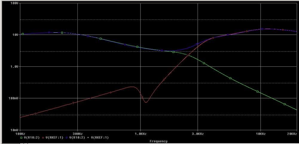
At ~1.1kHz, the voltage is snubbed and prevent the T27a from seeing the offending frequency. Due to the drivers own SPL responses, anything below 1.5khz will have very little output.
At 3kHz the knee kink as in the case of 104, is removed and the transition smoothed. This would make the speaker sound less intrusive.
The B200 transition is also smoothed near the 2-2.5kHz region. The 2.5kHz region determines the perceived sound quality of the speakers.
At 2.5khz, the summed voltages appear to be smooth and no exaggeration between the 2.5khz to above 3khz. This is a marked improvement over the 104 crossover.
The boost above 10khz for the T27 remains. The output is similar to the 104 crossover.
The analysis shows that the KEF 104aB crossover is tweaked to suit the T27a characteristics. KEF's acoustic Butterworth article might not had elaborated much in these technical details. The snubbing effect appears to be a KEF special. This same designs appears in later KEF models such as the Carlton series.
As such, it is not advisable to replace the T27a with any other driver without due consideration of the high pass circuit design. It would be better to source for a pair of used T27a (measured at 6.5ohms dc resistance) than to put in a pair of Seas or Vifa unit (resonant points can be anywhere from 900Hz to 1.2kHz, and different response curves).
Real World Components
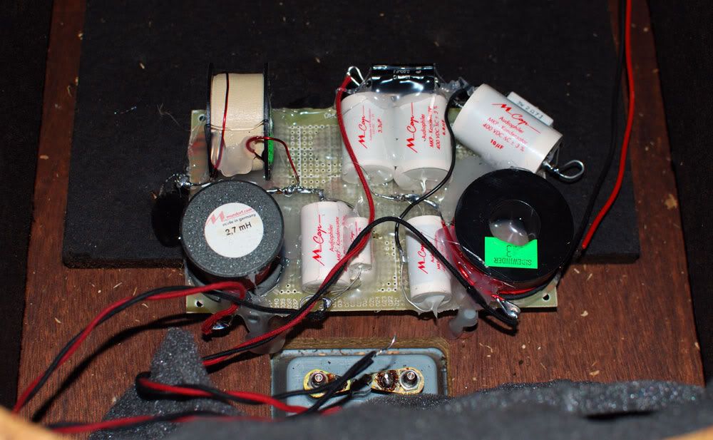
A new cross over is constructed using direct point to point connection of components. Components are secured on a FR4 board using hot glue. The final cross over is also placed near the input terminals, far away from the magnetic field of the speaker drivers.
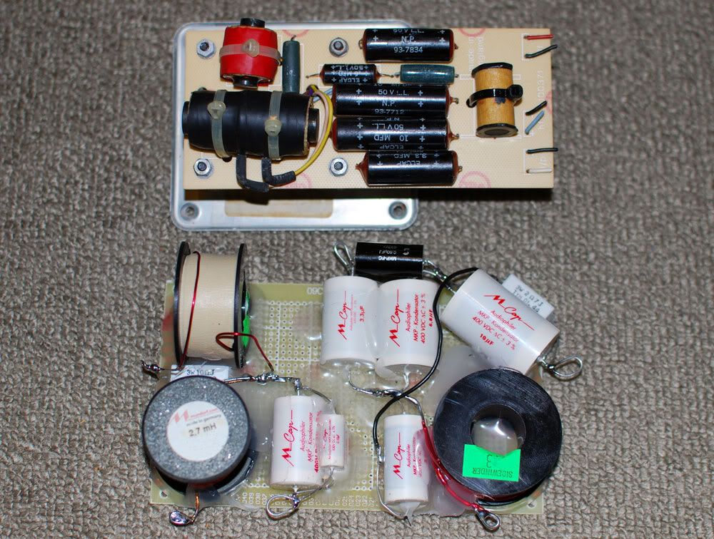
The main inductors can be of the Mundorff cored coil for its low series R and low hysteresis. The other two cores can be air core units but low series R as well. The inductors should be measured to ensure it is within 1% of the value stated.
The capacitors were chose to be Mundorff M caps (400-630V) types. The Mundorff caps are sonically superior to the Solen fast caps; both with a very similar cost. There is no need to bypass each cap with a 0.1 or 0.01uf cap, as this may result in a worse perceived high frequency. Individual caps should be measured for correct values.
The tolerance of the M cap is at 2%, at two extremes the values can be, in the case of 5uf theoretical, be 4.9u against 5.1u. This is not a lot, but we want to be accurate from the start. In the case of 10% tolerances, the deviation could be 4.5u or 5.5u, which will have significant shift in the cross over frequencies.
For internal wiring, it is recommended to use single core 18 or 16 gauge pure copper wires. As the crossover is nearer to the terminals, the overall wire run length is much reduced for the bass driver. The longer wire run for the T27a has little effect, as it favors a slightly higher series resistance. The coil inductance of the driver is much higher than the magnitude of the internal wiring. For the safety of the T27a, the 1 amp fast blow fuse should be in place.
The B200 drivers can still be sourced occasionally on Ebay UK. The drivers should have the same series resistance s and deviate very little from the spec of 7 ohm dc. Due to age, the driver coil may see loose particles in the air gap, or the coil former may be deformed due to heat. This can be checked by slightly depressing the cone and check for rubbing of coil on the magnets. The damaged coil may be repaired, but not many technicians are willing to do it these days.
The bass driver and the passive radiator should have the rubber suspension cleaned and treated by Armor All. The rubber suspension may become dry and brittle in some cases. The change in compliance of the suspension will surely change the sound.
The drivers must be installed with sealing gaskets/foams so that everything is air tight. Check by slightly depressing the main driver, and see a small following excursion on the bass radiator. If the bass radiator do not follow suit, there is leakage.
The new cross over would require at least 100 hours to break in, mainly due to the capacitors. New capacitors will always ‘sound’ closed in, compressed when new. Breaking in over 100 or even 200 hours will significantly improve the sound. Therefore, initial assessment of sound quality when the crossovers are brand new will surely result in a wrong conclusion.
With the new crossover installed with the good drivers, the speakers can sound close to what it was designed for, and even better.
Comparing the original 104 and new 104aB, the mid range is less bloated and high frequency is less piercing, even thought the 104 have higher series resistance caps. Bass is more extended and the speakers sound a few classes higher. The new 104aB sound more refined, fast, detailed and still musical. However, the 104 still holds its charm, mainly due to its coloration which many find it pleasing.
Comparing the original 104aB and the new 104aB, there are more details in the modern version with the equivalent sweetness. Bass is less muddled. The speakers appear to have a ‘lower’ sensitivity, as the volume control can be turned a few notches higher. In reality, the speaker can play music louder, with much lesser fatigue to the ears. The most significant different will be the speed of the speakers. The speaker will be able to handle transients much better. Cymbals and percussion sound more clear but less edgy.
As the crossovers continue to break in with the drivers, sonic spatial illusion becomes wickedly apparent. Separation of individual instruments is improved, and vocals become more life-like. Sound stage layering will be more distinct.
In conclusion, the old caps in these old speakers must be replaced. There is a choice of original Alcaps or Mundorff depending on personal preferences. The old inductors can be replaced by modern cores that will elevate the performance of the speakers. The internal wires are too thin and relocating the crossovers is advantageous (foregoing the facility of inductance change for equalization).
A new cross over is not expensive to build, and the old crossover can be retained for comparisons, or for display. This is a worthy upgrade; the returns are much greater than buying a new amplifier or even a new pair of modern speakers.
To fully appreciate the KEF 104aB, a high quality solid state amplifier of about 80-100Watts is recommended. Tube amplifiers either push pull or single ended above 10Watts can have good results as the speaker has decent efficiency. The source should be a good LP setup to fully demonstrate the capabilities of these classic speakers. KEF 104 can response up to 30kHz range. There are not many modern speakers that can sound as marvelous as these classics.
- Home
- Loudspeakers
- Multi-Way
- KEF 104 to KEF 104aB mkII with SPICE