Dear Keantoken,
I read on internet said.
Schottky diodes are mainly used in applications that require fast response to changes in operation.
Some of the applications include
• Switching Power Supplies
• Switching Voltage Regulators
• Rectifiers
• Detectors
• Motor Drivers
The main disadvantage of a schottky diode is that it has a relatively high
reverse current (high leakage current).
Not available in ratings higher than about 100V
Please advise if below schottky diode can be use in KM and better than 1N400X
MBR1100, 1 Ampere, 100 Volt Schottky Barrier Rectifier
SB1100, 1 Amprere, 100 volts, Schottky Barrier Rectifier
SB1H100, 1 Ampere, 100 Volts Schottky Rectifier
SR1200, 1 Ampere, 200 Volts, Schottky Barrier Rectifier
Best regards,
Sun
Dear Keantoken,
I have finish PCB layout, would like to take your advice and suggestion.
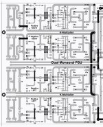
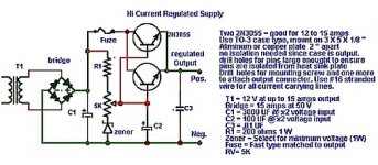
I attached herewith the PCB layout, top view and simple voltage regulator schematic.
The PCB size 23 cm x 32 cm, double side and dual monaural power supply design.
I am worry about grounding, it is correct my layout for Star Ground Point.
From PCB grounding to chassis connection via 10 Ohm resistor parallel with
100 nF cap and Diode.
For voltage regulator I am using D44H11 for positive and D45H11 for negative.
D44H11 and D45H11, complementary power transistor (80V, 10A, 50W)
they are intended for general purpose linear and switching applications.
Do you think D44H11 and D45H11 quite enough for KM or have to replace
with High Speed Switching Transistor..?
I never read any discussion regarding place of voltage regulator before
or after KM, so I think before KM there is no effect to the KM to works.
If every thing is OK, I will start to order parts to Mouser and Parts Connexion.
I plan to use Nichicon KG, Nichicon KZ, Elna RFS and Elna ROA,
Vishay MKP 1837 for capacitor and PRP or Dale Resistor.
To get optimum performance of capacitor I will paralel
Nichicon KG or Nichicon KZ paralel with Elna RFS and Elna ROA with Elna RFS.
Thanks for your kind attention and help.
Best regards,
Sun
I have finish PCB layout, would like to take your advice and suggestion.
I attached herewith the PCB layout, top view and simple voltage regulator schematic.
The PCB size 23 cm x 32 cm, double side and dual monaural power supply design.
I am worry about grounding, it is correct my layout for Star Ground Point.
From PCB grounding to chassis connection via 10 Ohm resistor parallel with
100 nF cap and Diode.
For voltage regulator I am using D44H11 for positive and D45H11 for negative.
D44H11 and D45H11, complementary power transistor (80V, 10A, 50W)
they are intended for general purpose linear and switching applications.
Do you think D44H11 and D45H11 quite enough for KM or have to replace
with High Speed Switching Transistor..?
I never read any discussion regarding place of voltage regulator before
or after KM, so I think before KM there is no effect to the KM to works.
If every thing is OK, I will start to order parts to Mouser and Parts Connexion.
I plan to use Nichicon KG, Nichicon KZ, Elna RFS and Elna ROA,
Vishay MKP 1837 for capacitor and PRP or Dale Resistor.
To get optimum performance of capacitor I will paralel
Nichicon KG or Nichicon KZ paralel with Elna RFS and Elna ROA with Elna RFS.
Thanks for your kind attention and help.
Best regards,
Sun
Attachments
That voltage regulator will be okay for filtering, but it's output impedance will be lower than the KM. So in this case I would suggest putting the regulator before the KM.
The D4xH11 are good at their power range, but overkill. Why not use 2SC5171 like the Kmultipliers? Then you get a quantity discount and you don't use any slower transistor than necessary.
That PCB is very nice looking. What program do you use to make it? I can't see any problems so far.
The D4xH11 are good at their power range, but overkill. Why not use 2SC5171 like the Kmultipliers? Then you get a quantity discount and you don't use any slower transistor than necessary.
That PCB is very nice looking. What program do you use to make it? I can't see any problems so far.
Dear Keantoken,
Thanks and appreciated to you for suggestion.
I will order 2SC6171 and complementary to replace D4xH11.
PCB layout make by Adobe Photoshop.
I will report the result, maybe take view weeks or months.
Now I start to order parts and PCB to the PCB maker in my country.
Best regards,
Sun
Thanks and appreciated to you for suggestion.
I will order 2SC6171 and complementary to replace D4xH11.
PCB layout make by Adobe Photoshop.
I will report the result, maybe take view weeks or months.
Now I start to order parts and PCB to the PCB maker in my country.
Best regards,
Sun
I thought you normally recommend the lowest output impedance device last in the sequence so that the client circuit sees the benefit of lowest source impedance.....voltage regulator .....it's output impedance will be lower than the KM. So in this case I would suggest putting the regulator before the KM..................
Are you confirming that
....voltage regulator .....it's output impedance will be HIGHER than the KM. So in this case I would suggest putting the regulator before the KM..................
should have said::
Originally Posted by keantoken
....voltage regulator .....it's output impedance will be lower than the KM. So in this case I would suggest putting the regulator before the KM..................
....voltage regulator .....it's output impedance will be HIGHER than the KM. So in this case I would suggest putting the regulator before the KM..................
Hi keantoken,
Thank you very much for your help.
Please see http://www.diyaudio.com/forums/head...mk-ii-headphone-amplifier-20.html#post3979007
193,194,195.
Thank you very much for your help.
Please see http://www.diyaudio.com/forums/head...mk-ii-headphone-amplifier-20.html#post3979007
193,194,195.
I don’t want to go over the theory of operation for K-Multiplier since you can read all that info directly from Keantoken's webpage, but I’ll share with my experience of usage of his creature. I have 3 month of listening by now and I can summarize all what I have from Keantoken's devise. I use one in my Salas Phono (MC setup) external Raw PSU and second one in my J-Mo Mk II headphone amplifier (single box for all components).
About Phono: First of all, I contracted simplistic PSU based on FSP manual and this is how I tested and adjusted FSP. The sound was amazing as most of DYIers reported. However, I experienced with obvious hum which I got at listening level of my volume knob. All GND connections were checked and rechecked several times for loops. I tried to rearrange components and GND several times. No change. Hum was there and at high volume it was a dominant. After some scope test I figure out that my voltage ripple was about 300mV. So, I constructed simple C-Multiplier and hum dropped quite a bit, but still there.
Then, I removed it and I installed Hammond 10H 300mA choke and hum is disappeared. It was nice development and positive outcome. But…., I can’t use artillery size transformer. My PSU box was tiny for it. Second concern was related to its price. It is about $80 a piece and I need two. So, I asked Keantoken to help me to test his K-Multilier and he physically build one for me. PCB was made by Bill Louey from Australia. So and again, I used classic Raw DC found in Salas manual and added K-Multiplier to its output. Same effect as with Hammond. Quite and I had no any noise at all with max volume. BTW, TT was disconnected. I have some very small background noise at absolute max volume when I connect my TT, but that is related to my cartridge air pickup, not to PSU or FSP. For my case and for my FSP – it was definitely worth it to use K-Muli.
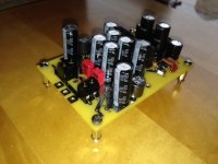
About J-Mo Mk II headphone amplifier: There, I used K-Multiplier assembled on the same Bill’s single PCB with full Raw PSU: rectifiers, caps, small chokes and ect.
That board feed Salas BIB shunts, and these feed amplifier. Not a buzz. Absolutely quite. With that amp and with such arrangement, I got sound that I never experienced before from Digital source.
For these guys who is enclosure space limited and looking for elegant way of ripple rejection treatment for the sensitive circuits like MC phono, headphone amplifier, impedance matching buffers and ect.., K-Mulitiplier is the solution!
About Phono: First of all, I contracted simplistic PSU based on FSP manual and this is how I tested and adjusted FSP. The sound was amazing as most of DYIers reported. However, I experienced with obvious hum which I got at listening level of my volume knob. All GND connections were checked and rechecked several times for loops. I tried to rearrange components and GND several times. No change. Hum was there and at high volume it was a dominant. After some scope test I figure out that my voltage ripple was about 300mV. So, I constructed simple C-Multiplier and hum dropped quite a bit, but still there.
Then, I removed it and I installed Hammond 10H 300mA choke and hum is disappeared. It was nice development and positive outcome. But…., I can’t use artillery size transformer. My PSU box was tiny for it. Second concern was related to its price. It is about $80 a piece and I need two. So, I asked Keantoken to help me to test his K-Multilier and he physically build one for me. PCB was made by Bill Louey from Australia. So and again, I used classic Raw DC found in Salas manual and added K-Multiplier to its output. Same effect as with Hammond. Quite and I had no any noise at all with max volume. BTW, TT was disconnected. I have some very small background noise at absolute max volume when I connect my TT, but that is related to my cartridge air pickup, not to PSU or FSP. For my case and for my FSP – it was definitely worth it to use K-Muli.
About J-Mo Mk II headphone amplifier: There, I used K-Multiplier assembled on the same Bill’s single PCB with full Raw PSU: rectifiers, caps, small chokes and ect.
That board feed Salas BIB shunts, and these feed amplifier. Not a buzz. Absolutely quite. With that amp and with such arrangement, I got sound that I never experienced before from Digital source.
For these guys who is enclosure space limited and looking for elegant way of ripple rejection treatment for the sensitive circuits like MC phono, headphone amplifier, impedance matching buffers and ect.., K-Mulitiplier is the solution!
Attachments
")
It depends on whether your circuit needs more PSRR or more stable rails. The LM317 itself benefits from filtered input if there are transients on the input such as from a switching regulator. However these chipregs tend to resonate with output capacitors to create noise peaks.
Personally, I would try putting the KM after the LM317, because in my experience the output impedance is reasonably low and the LM317 is very noisy. And if I wasn't satisfied I would swap them and check the other way. You may plan your layout so that this is easy to do. Not many people have tried both configurations, so I can't say which is most preferred.
Personally, I would try putting the KM after the LM317, because in my experience the output impedance is reasonably low and the LM317 is very noisy. And if I wasn't satisfied I would swap them and check the other way. You may plan your layout so that this is easy to do. Not many people have tried both configurations, so I can't say which is most preferred.
With further tweaking it's making the amplifier, as in I wouldn't want to go without it. What it does is pretty special. If you've got a lack of control from integrated devices of any type, this provides a pretty incredible amount of voicing. I'd try it for OPAMP's and other low power devices. I'm sure it would be pretty interesting for small class D as well.
- Home
- Amplifiers
- Power Supplies
- Keantoken's CFP cap multiplier