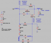
Okay... Getting there. Vbc(Q2) is lower than the total voltage drop which must mean there is another broken joint? What is the voltage across R1? Vbe of 1.15V for Q1 means it is probably dead... But I don't know why that would happen. Q1's pinout is CBE looking at the flat side.
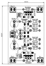
The layout appears to be correct based on my guesses of where the pins are.
The layout appears to be correct based on my guesses of where the pins are.
hi kean,
do you mean Vce(Q2)?, i try to simulate with ltspice and Vbc(Q2) is less than Vdrop
Vce(Q2) = Vdrop
something wrong with my part,
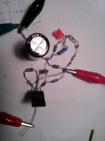
here my real measurement
Q2
Vbe -0.62mv
Vce -2.4 v
Vbc 1.43 v
Q1
Vbe 1.15v (???)
Vce 1.46v
Vbc -0.7v
do you mean Vce(Q2)?, i try to simulate with ltspice and Vbc(Q2) is less than Vdrop
Vce(Q2) = Vdrop
something wrong with my part,
here my real measurement
Q2
Vbe -0.62mv
Vce -2.4 v
Vbc 1.43 v
Q1
Vbe 1.15v (???)
Vce 1.46v
Vbc -0.7v
Attachments
Yes, I meant Vce.
Okay... Vbe-Vbc=Vce. For some reason this doesn't hold up in your measurements. In any case a Vbe of 1.15V means Q1 is fried; replace it, or test it for Hfe in case it really isn't bad, of which there is a remote chance.
If that doesn't work, add a lytic of any size to the input. Your goal is to get output AC below 1mV. With 136mV input it should be at least .27mV. Until then the circuit is still broken. If this doesn't work, then I'm flabbergasted.
Last edited:
That all looks right, except your input-output DC gives 1.4V whereas Vce(Q2) is -1.8V... And output AC is still way too high. And how did Q1 get fried!?
I'm sorry this is taking so long. How long do you wait after turning it on to measure it?
Measure again with 1k resistors in series with each probe, and the probe wires twisted. If this doesn't make the measurements consistent, then I think your meter must be flaky.
I'm sorry this is taking so long. How long do you wait after turning it on to measure it?
Measure again with 1k resistors in series with each probe, and the probe wires twisted. If this doesn't make the measurements consistent, then I think your meter must be flaky.
Tinitus, anything interesting about the sound? Or does it just do what you expected?
on my bass ? .... best I have had yet, or actually, much better, and almost where I want it
all commercial units are now out of my system
I can explain it very simple
there is none of all the strange ressonances or artefacts that plagued me a lot before
and now I can always find a setting that sounds right
also very nice that I don't need the compressor either
may be the compressor works better now, I don't know
but I don't need it, thats certain
actually, I still need that buffer, and with +/- symmetric power supply
so the next will also have your negative k-multiplier
")
Actually, found this in another thread. Is this the one you're using?
.MODEL Q2SA1930 PNP(
+ IS=10.000E-15
+ BF=210
+ VAF=78
+ IKF=10.000E-3
+ XTB=1.5
+ BR=.1001
+ VAR=100
+ IKR=10.000E-3
+ ISC=10.000E-15
+ CJE=3.252E-12
+ CJC=63.196E-12
+ MJC=.33333
+ TF=83.239E-12
+ XTF=10
+ VTF=10
+ ITF=1)
.MODEL Q2SA1930 PNP(
+ IS=10.000E-15
+ BF=210
+ VAF=78
+ IKF=10.000E-3
+ XTB=1.5
+ BR=.1001
+ VAR=100
+ IKR=10.000E-3
+ ISC=10.000E-15
+ CJE=3.252E-12
+ CJC=63.196E-12
+ MJC=.33333
+ TF=83.239E-12
+ XTF=10
+ VTF=10
+ ITF=1)
That all looks right, except your input-output DC gives 1.4V whereas Vce(Q2) is -1.8V... And output AC is still way too high. And how did Q1 get fried!?
I'm sorry this is taking so long. How long do you wait after turning it on to measure it?
Measure again with 1k resistors in series with each probe, and the probe wires twisted. If this doesn't make the measurements consistent, then I think your meter must be flaky.
q1 dead when i try to add elco paralleled to R load and i forget to power off. i measured rigth after turn it on and wait 3-5 minutes.
no problem kean, i happy you help me alot.
i gues my meter was flaky. i'll do your suggestion and report back.
thank you
naf
Here they are. I was searching for the wrong terms. I was worried Harry had been entirely deleted from DIYAudio!
http://www.diyaudio.com/forums/solid-state/2374-finding-spice-models-2.html#post3083728
http://www.diyaudio.com/forums/solid-state/2374-finding-spice-models-2.html#post3083728
q1 dead when i try to add elco paralleled to R load and i forget to power off. i measured rigth after turn it on and wait 3-5 minutes.
In that case Q2 may be damaged as well, so you may want to check. The rugged BC3x7 has a surge SOA of 1A, and drawing over 1A through the base of Q2 could be an issue...
Hi kean,
replacing Q2, twisting wire and adding 1k resistor on each probe
here my measurment
DC in 23.01v
DC out 21,3v
AC in 0.170v
AC out 0.126v
Q2 (change to SA1943)
Vbc 1.29v
Vbe -0.569v
Vce -1.87v
Q1
Vbc -0.73v
Vbe 0.476v
Vce -1.38v
I think my meter was flaky when measuring small AC signal.
thank you
naf
A flaky meter is totally unacceptable. I would get a new one. The measurements are a bit more consistent this time.
thank you kean
- Home
- Amplifiers
- Power Supplies
- Keantoken's CFP cap multiplier