 now I'm back to it.
What's the DC voltage on all 8 pins of the LM293 on the audio driver board?
Pin 1: 6.69v
Pin 2: 2.46
Pin 3: 9.79
Pin 4: 0
Pin 5: 1.02
Pin 6: 3.17
Pin 7: 0.168
Pin 8: 12.77
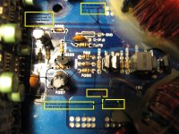
Pretty close to what they were in post 5. Pin 3 is way over... just can't figure out what is driving it that high... there is a zener diode that attaches to pin 11 on the driver board. It has the same voltage across it as pin 3 on the 293... 9.77v. Its board designation is @ D206. Does that voltage seem right?
Attachments
Last edited:
Oops... just noticed you asked for the "audio driver board".... There is 0.000 v on every pin of the 293 on the audio driver card. There is 0.000v on every pin of the audio driver card except pin 2-1 it has 9.88v. I started to test U2. pin 1 had 0.40v and 2 had 0.126v all the rest 0.000 then pins 1 and 2 had 0.3v on each... then retested and got 0.000v on both, now they read .065v. black lead on transformer secondary center. There is 0.000v on every pin of U3 also.
Last edited:
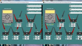
I'm not completely sure how to check them properly... They have 1D and 2D written on them. I lifted the Q 11 and Q7's back feet. Is there a section in your tutorial that goes over testing these specific type? I'm still looking but not having a whole lot of luck.
Last edited:
Well isn't that just the handiest way to compare and know you covered all the angles. Thanks. I couldn't find that in the tutorial.
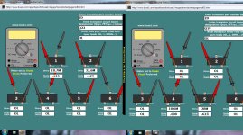
They all appear to be good. Any other ideas?
They all appear to be good.
Any other ideas?Attachments
Last edited:
I've been over them a couple times but they do have those white insulators over the outside legs. I'm quite certain they are good, but I'll check them again before removing the audio driver board. I've been testing them at the pads. Am I going to attempt to power it up with the audio driver board removed?
Last edited:
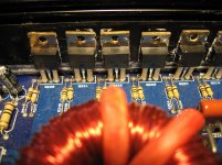
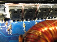
All the inputs are 064N`s. The outputs are both N and P. 640N`s and 9640`s.
The resistors on the output side are 10ohm and 20K. The gate resistors on the input section is 47ohm.
Where should this 100K be located around?
The resistors on the output side are 10ohm and 20K. The gate resistors on the input section is 47ohm.
Where should this 100K be located around?
Attachments
Last edited:
The IRFP064Ns and the associated components are the 'power supply' components, not 'input' components.
It appears that there are 10 ohm gate resistors and 100k ohm pulldown resistors. It would be safe to power it up without the driver board.
When you power it up, check the DC voltage on the drains of all of the output transistors. Do any have more than a fraction of a volt of DC?
It appears that there are 10 ohm gate resistors and 100k ohm pulldown resistors. It would be safe to power it up without the driver board.
When you power it up, check the DC voltage on the drains of all of the output transistors. Do any have more than a fraction of a volt of DC?
- Status
- This old topic is closed. If you want to reopen this topic, contact a moderator using the "Report Post" button.
- Home
- General Interest
- Car Audio
- KA7500bd Pin 1 high??? Brutus BXi2607D