I went here: http://www.t-linespeakers.org/projects/sampson/index.html
I am very intrigued by making a speaker out of actual pvc pipe. Before I try it, there are a couple of clarifications about the TL design I can't seem to track down satisfactorily.
Given: A Vifa P17WG00-06 (6.5") has Fs 35Hz. By my calculations, I need a pipe that's 2.357m in length.
1) What about pipe diameter?
2) Is resonant frequency all about volume, as in boxes, or is it something different?
3) Related to 2: I'll obviously have to bend the pipe at some point. How much does that effect the TL design? I'm thinking about this particular design:http://www.t-linespeakers.org/projects/sampson/fqwt.html
4) What are the actual problems I need to solve, i.e., what is the problem with actual PVC pipe that is different from the normal TL problems as can be solved by Martin King's calculations?
5) What is the difference between this design and the design of Planet10's nautilus design (closed end)?
Thanks, and these questions are, indeed, a result of massive research of this forum. You guys are the greatest.
Thanks,
Dave
PS--how do I update my profile on this forum? And, number 2 above seems stupid on the face of it, but I'm not quite clear on the whole concept, yet....
Hi Kneadle
Easy stuff first,
 )
)
I have been experimenting with this for a while, but basically the principle with a terminated line is that all the rearward sound is absorbed in the line, and none is used to reinforce the bottom end, as in a TQWL. So it will have the beneficial box loading on the driver of a TL, but no cabinet resonances, and a smoother roll off.
Easy stuff first,
Use the User CP button at the top, then you are given a couple of options on the menu bar to change things.PS--how do I update my profile on this forum
Pipe diameter has an effect on response, and I AFAIK it is a factor in MJK's simulation, ( I don't know for definate, as I havent got it working on my Mac yet) What about pipe diameter?
)Yes partly, but also about the length of the pipe, think pipe organs.Is resonant frequency all about volume, as in boxes, or is it something different?
It is best to have a straight pipe, but practicality usually means a bend or two.3) Related to 2: I'll obviously have to bend the pipe at some point. How much does that effect the TL design?
Again, AFAIK, Martins software should simulate this, you just need to set line taper to zero.4) What are the actual problems I need to solve, i.e., what is the problem with actual PVC pipe that is different
Good questionWhat is the difference between this design and the design of Planet10's nautilus design (closed end)?
I have been experimenting with this for a while, but basically the principle with a terminated line is that all the rearward sound is absorbed in the line, and none is used to reinforce the bottom end, as in a TQWL. So it will have the beneficial box loading on the driver of a TL, but no cabinet resonances, and a smoother roll off.Originally posted by pinkmouse
Easy stuff first,
Use the User CP button at the top, then you are given a couple of options on the menu bar to change things.
Thanks. Sometimes these are the hardest things to find.
So it will have the beneficial box loading on the driver of a TL, but no cabinet resonances, and a smoother roll off.
I should add, then, that smooth rolloff is what I want. I'm trying to avoid the big dip at the end of the frequency spectrum. I had a box designed that modelled an F3 from 75-40. But then it just bottoms out. It seems like a TL is designed to extend the rolloff a bit further and at a gentler slope than a box.
Thanks,
Dave
One Quick Question
I'm using King's TL Open End to do calculations for my TL imaginings. The "Resulting Acoustic Impedance for the Transmission Line" never seems to flatten out.
Is that the way it's actually supposed to be? A hump on the Magnitude and a soft dip on the Phase?
Thanks,
Dave
I'm using King's TL Open End to do calculations for my TL imaginings. The "Resulting Acoustic Impedance for the Transmission Line" never seems to flatten out.
Is that the way it's actually supposed to be? A hump on the Magnitude and a soft dip on the Phase?
Thanks,
Dave
Hi Dave,
The "Resulting Acoustic Impedance for the Transmission Line" is intended to show the tuning frequency of the line, it is a quantity that cannot be measured directly. Use this plot to check the first peak to see at what frequency your TL is tuned.
By flattening the impedance I think you intended to look at the "Transmission Line System and Infinite Baffle Impedance" plot near the end of the worksheet. This is the electrical impedance as measured at the speaker terminals. As damping material is added the peaks in this plot will tend to broaden and flatten out.
Hope that helps,
Man, this is a great program.
While I have the master's ear (or keyboard), can you tell me what I should be looking for as far as a bona-fide design error might be?
That is, which kind of bump in a given design would indicate a real problem? I'm not terribly familiar with these kinds of graphs, I must admit.
Thanks a million,
Dave
PS--is all of the Enclosure Geometry Definition in imperial units, or is the So and SL in sq. cm.?
Hi Dave,
Up above you wrote :
"I should add, then, that smooth rolloff is what I want. I'm trying to avoid the big dip at the end of the frequency spectrum. I had a box designed that modelled an F3 from 75-40. But then it just bottoms out. It seems like a TL is designed to extend the rolloff a bit further and at a gentler slope than a box."
I think that you are on the right track. If you look at my Focal TL vs the two Fostex mass loaded pipes you will see in the Focal just what you descibed. The bass in the Focal system does not appear to go as low as the mass loaded Fostex designs but it sounds like it goes much lower. I think that the more gradual roll-off coupled with the room reinforcement balances out very nicely.
So when designing a TL, I watch the system SPL response to see the real potential. I watch the woofer and the terminus SPL's to try and understand what is going on in the line. I watch the impulse response in the time domain to see if reflections cause secondary peaks. I fiddle with the geometry S0, SL, and the driver offset. I mess with the stuffing density, and placement, trying to get a slow roll-off in the bass. I increase the area to improve the quantitiy of bass until I reach a level of diminishing return or the enclosure gets way too big. I iterate the design on and off for a week until I have found what I believe is an optimum configuration. Then I start again with a different style of geometry. I know this sounds very unscientific but this is how I work and after a while you get somewhat of an intuitive feel. Take a peak at Bob Brines' site (linked form mine), he has some really good recommendations for geometries which I also follow.
As for the units, you can enter any set of inconsistent units you want. MathCad immediately converts whatever screwed up set you enter into MKS and calculates using these values. I have set the units on the plotted data. The units feature is what I really like about MathCad, I tend to input T/S parameters in metric and TL geometry in english.
Hope that helps,
MJK said:I know this sounds very unscientific but this is how I work and after a while you get somewhat of an intuitive feel.
At the risk of becoming unpopular, I will only say that it's this aspect of TL that has me excited. Not that the science of other DIY is boring and dull, but I actually like the risk that one seems to take in designing a TL system, and the risk includes almost every aspect of design. You just wait, my friend, for the design I shall unleash here in the following weeks.
Hope that helps,
Indeed it does. If it were Christmas, I'd say, "and visions of PVC pipe danced in their heads."
But it's not, so I won't.
Thanks,
David Duke
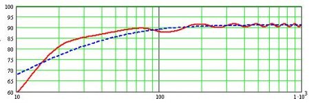
this looks pretty smooth
The design so far has its acoustic impedance at around 20Hz, and the attached file (FField TL SPL Response) shows the sloooooow rolloff.
There are a few design problems left, but if I stopped modeling right now, I'd end up with a heck of a T-Line system.
That is, unless I'm completely blind to something obviously wrong with the idea.

Thanks Martin,
Dave
The design so far has its acoustic impedance at around 20Hz, and the attached file (FField TL SPL Response) shows the sloooooow rolloff.
There are a few design problems left, but if I stopped modeling right now, I'd end up with a heck of a T-Line system.
That is, unless I'm completely blind to something obviously wrong with the idea.
Thanks Martin,
Dave
Attachments
Hi Dave,
Couple of points :
1) My goal is to take the risk out of TL design using the MathCad worksheets. So far I have always had very good correlation between calculated design and finished speaker. Since a TL has an number of configurations that will yield a similar reponse you can be more creative, hopefully that is what you ment to say.
2) You have tuned your TL very low, which is OK assuming that you have measured your driver's T/S parameters. If you are using spec sheet parameters you might want to hedge your bet and tune a little higher. Most manufacturers seem to tilt the specs a little towards lower fs values. I would probably tune your TL a little higher anyway, but that is just my taste.
3) It looks like you are using the "TL Open End" worksheet. If you try the "TL Offset Driver" worksheet you can further smooth the ripple by placing the driver at about 1/3 of the length from the closed end, assuming a straight pipe. Your ripple looks very small but you might do a little bit better.
But overall the design looks good based on the plot you have posted. I'll be interested in hearing how it turns out.
Martin,
You're correct. 20Hz is a little ambitious, I think, and unecessary. The manufacturer's fs is at 35, and I doubt it actually resonates that low in "real" life.
But I always get confused at that point. The joy of all this is the "relativity" of the whole thing. Thanks to the mathcad production you have for us, I can get a fantastic design even if it turns out not to be dead-on accurate for me, an amateur.
I'll only tantalize you by saying that I'm going to use some ideas I got for other resonating objects to design this creature.
Stay tuned!
Dave
- Status
- This old topic is closed. If you want to reopen this topic, contact a moderator using the "Report Post" button.
- Home
- Loudspeakers
- Multi-Way
- Just a few Transmission Line Questions