I'm tidying up an old build - a 49810/thermaltrak build from panson audio. I wanted to see if improving the power supply would improve the sound. I could run a few dropping diodes, but it would be more elegant to adjust downwards if possible. It looks like adjusting R2/R3 and/or the pot should change the voltage divider on the base of the transistor? I confess I haven't had time to go checking out voltages at all these parts, I hope to get at it tonight.
The transformer is putting out 37v AC, and I can adjust from 43v or so upwards to the drop.
The transformer is putting out 37v AC, and I can adjust from 43v or so upwards to the drop.
Fran, the Cap Mx boards you have take DC input and you say you need to drop from 43V DC to 35V DC. As pointed out the pots on the Cap Mx boards are for balancing the +/– output rails. You will not be able to drop down to 35 or 38V. I suggest using DC DC step down converters. They are cheap and work very well to balance the +/- rails even before you feed the Cap Mx. Just get ones that can handle sufficient current.I'm using an old but beefy transformer for a build, (37VAC) and I have about 43V DC at the bottom of the range. I need to get to about 35-38 V if at all possible for the amp circuit that its to power.
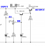
The output is simply the voltage at node BB, minus two emitter follower drops.
To decrease the output voltage, either change the emitter follower drops (difficult), or change the voltage at node BB (easy). Increasing the resistance of R2 will decrease the voltage at node BB. Decreasing R3 will do the same thing. Personally I prefer increasing R2, because it lowers the lowpass corner frequency set by R2 and C3.
The trimmer pot intentionally has a small adjustment range, and is only used for final tuning. Its original purpose was to let you tweak the circuit for minimum possible in-to-out drop (i.e. the maximum possible output voltage) with little or no output ripple. Connect the heaviest possible load, monitor the output with an oscilloscope (AC coupling), and dial the output voltage upwards very slooooowly. When ripple just barely appears, dial back a teeny bit, then stop.
_
Attachments
The Mark Johnson cap Mx is a different topology - it’s a BJT in Darlington, if I recall. It does have variable voltage drop but not meant to be a big regulator like a 78xx style. Easiest way to get more drop is add a CRC and make R a bit larger like 0.22R. Make sure you have enough power rating on resistors as they get hot. 1A10 diodes in series are good for 0.6v each.
edit: I see MJ already replied.
edit: I see MJ already replied.
Mark, All,The output is simply the voltage at node BB, minus two emitter follower drops.
To decrease the output voltage, either change the emitter follower drops (difficult), or change the voltage at node BB (easy). Increasing the resistance of R2 will decrease the voltage at node BB. Decreasing R3 will do the same thing. Personally I prefer increasing R2, because it lowers the lowpass corner frequency set by R2 and C3.
The trimmer pot intentionally has a small adjustment range, and is only used for final tuning. Its original purpose was to let you tweak the circuit for minimum possible in-to-out drop (i.e. the maximum possible output voltage) with little or no output ripple. Connect the heaviest possible load, monitor the output with an oscilloscope (AC coupling), and dial the output voltage upwards very slooooowly. When ripple just barely appears, dial back a teeny bit, then stop.
_
Many thanks for your answers on this. I installed a pot for R2/R6 on that schematic this evening, and adjusted to get the voltage range I needed. I took back out the pot and put back in a fixed resistor of the right value then. This gives me about 4V adjustment either way and I can hold the voltage where I need it.
Many thanks for these boards and your time designing the boards. I will be using these for sure in the future again. This build went into a chip amp, but the next one will be something different, maybe a phonostage or something.
Thanks again
Fran
diyAudio member Prasi did all the work, converting a quick and dirty thread-message schematic I sketched off-handed, into a very nice PCB layout. BTW if you own a curve tracer that'll go up to 1 ampere, you can choose transistors that will give much better ripple attenuation in Cap Multipliers [both darlington and Sziklai/CFP]. The trick is to find power devices with acceptable Safe Operating Area limits, that also have the very highest Early Voltage of all the ones you tested. It'll cost you $40 to buy plenty of different candidate parts to test, and then another $3-4 to buy some more of the winner.
wikipedia link
Univ. Maryland link
YouTube video #1
YouTube video #2
wikipedia link
Univ. Maryland link
YouTube video #1
YouTube video #2
Last edited:
Yeah, so unfortunately its clear that there is sonic benefit on this amp at least to add a CRC after the cap-mx. I used 10kuF-1R-10kuF nichicon audio grade - the black ones with the gold writing. Its most noticeable on high dynamic impacts - these are more emphasised.
Anyway, this commentary probably doesn't belong in this thread, and I don 't want to clutter the thread up but thought it might be worth it for other builders.
Anyway, this commentary probably doesn't belong in this thread, and I don 't want to clutter the thread up but thought it might be worth it for other builders.
I managed to measure with an RMS DMM my cap mx effects. I have 3 DMM that are supposed to do RMS AC but only one gives me a reading.
So this is approx 50vdc feeding a TPA3255 amp through about 30000uf cap bank.
Using the small break out boards as seen on the LT4320 thread I believe.
Amp playing music at approx half volume.
Pre capmx sees the AC fluctuated up to a max of 10mv.
Post capmx and the AC peaks st sub 1mv.
Music playing quite loudly, pre capmx and peaks towards 100mv, probably averages 50mv
Post capmx and I see sub 10mv at all times.
Good stuff considering the small amount of added capacitance.
Intending on using a bigger capmx board for my upcoming Aleph 30. Need to look heatsinking requirements for it.
@jimk04 I built up a pair of these boards using BJTs and got to test them with a load last night in preparation for a new Aleph build. I fed them rectified DC from 25Vac transformer, single bridge with the centre taps (centre windings) to ground. I loaded the outputs with 8R power resistor, so that meant that under load the output did sag a little, pulling 3.5A from each rail, by about 2V or so over the normal 2-3V drop through the BJTs. In short, this means under load there was about 5V rail drop total. When I scoped this, when under load, there was about 5mV ripple. Adjusting the pots (installed at their mid point) didn't reduce this further, but going the other way on the pots, you could see the ripple rise. I have not yet had a look with a smaller load. The BJTs were mounted on a heatsink and they were barely warm. I think it might be safe to bolt them to the chassis floor, maybe mounted on a piece of aluminium, but I think I can get away without mounting them on the heatsink.
BTW, the advice I got elsewhere here says that you will still need a capacitance bank after the Cap-mx - so my own plan is to use a CRC of 10kuF-0r47-10kuF after it which might knock ripple a little more. Maybe I can try 1r0 etc and see what happens.
BTW, the advice I got elsewhere here says that you will still need a capacitance bank after the Cap-mx - so my own plan is to use a CRC of 10kuF-0r47-10kuF after it which might knock ripple a little more. Maybe I can try 1r0 etc and see what happens.
Thats interesting Fran thanks for that. Which BJTs?
5mv seems good for a class a type load. I've bought some 100w 12r resistors to try ro simulate the Aleph load. I now have a 2x25v Toroidy. I think I shall use 2 x BR. I've ordered some of bigger dual Capmx boards, with 2 outputs...1x +/-, not the 4 output like I sent you. That way I can maybe mount them one per side feeding each channel separately, hence 2 BR.
That's my thinking anyway!

Very neat @jimk04 - I used 2sc5200/2sa1943 - I had a few of them here, so built with those. Like you, I'm going dual mono on the supplies, so I ended up building 2 x cap-mx, just so that if they are getting warm I can separate them out onto each heatsink. The main reason for the experiment was to make sure the cap-mx can cope with the class A load, but its fairly clear that it will.
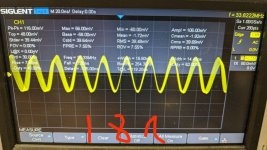
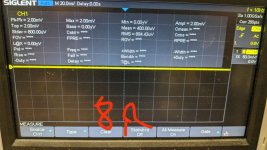
Mmmm. So i did another experiment there now. Testing the same cap-mx with both 8R load and 18R load (same load on both rails), representing 3.5A/1.5A or thereabouts. I get very little noise at 3.5A, but quite a bit at 1.5A. What am I doing wrong? This doesn't look like ripple to me, but some other noise or oscillation up at 33mHz?
The two scope shots are with the same settings, excuse my bad doodling, and yes there are extra stray wires used to hook up the extra resistors to give 18R.
The two scope shots are with the same settings, excuse my bad doodling, and yes there are extra stray wires used to hook up the extra resistors to give 18R.
Attachments
Sorry I can't help there Fran.
Just rigged up my potential Aleph PSU but I'm not sure it will be suitable as is.
18v Toroidy....not 25v! Gives 18v under the 12r load. Next to zero AC though on the DMM. Couldn't feel any heat in the mosfets but I soon turned it off (few minutes) as the power resistor was getting mighty warm.
I'll have to ask the Pass guys but I doubt 18v will cut it for an amp expecting 24.!
Hope you suss your issue. I have zero experience with scopes, albeit I did buy one recently!
Anyone able to hazard a guess? I hope to get back at this in the coming days, will test a second build to see if I can replicate what I'm seeing.Mmmm. So i did another experiment there now. Testing the same cap-mx with both 8R load and 18R load (same load on both rails), representing 3.5A/1.5A or thereabouts. I get very little noise at 3.5A, but quite a bit at 1.5A. What am I doing wrong? This doesn't look like ripple to me, but some other noise or oscillation up at 33mHz?
The two scope shots are with the same settings, excuse my bad doodling, and yes there are extra stray wires used to hook up the extra resistors to give 18R.
Anyone able to hazard a guess? I hope to get back at this in the coming days, will test a second build to see if I can replicate what I'm seeing.
What was the schematic that you followed for your build?
Also, any photos of how you currently have things laid out?
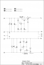
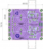
The schematic is attached, and the board is shown below - its the one linked in post 497. I don't have pics of the setup - but it is rough, test bench stuff. Transformer sitting on the bench, feeding a 25A bridge rectifier, then into the cap-mx board which is mounted on a heatsink, and then from the outputs to a resistive 8R/18R resistor load using jumpers with crocodile clips. So very much a quick test setup.
I reckoned I should be safe enough given that the PCB seems well tested, and the circuit is well used. I didn't think loose wiring would cause the noise I'm seeing..... and even if it did, I would have thought I would have seen that either with both loads, or higher on the heavier load.
I reckoned I should be safe enough given that the PCB seems well tested, and the circuit is well used. I didn't think loose wiring would cause the noise I'm seeing..... and even if it did, I would have thought I would have seen that either with both loads, or higher on the heavier load.
Attachments
I've built two of these (one for each channel of an amp I'm planning) but I haven't been able to get back to the bench to replicate this with the second build yet. Hopefully tomorrow night. If that one is OK then its definitely something with the build. All parts are as per the schematic, and all bought new from mouser except the 2SA1943/2SC5200 which came from working amps and tested OK on a transistor tester before installation and I used 15000uF capacitors for the main bank.
- Home
- Amplifiers
- Power Supplies
- Juma's Easy-Peasy Capacitance Multiplier