Anyone know anything about these 'infinite order' 120dB/Oct slope crossovers?
http://www.josephaudio.com/essay.islope.html
I'm curious
http://www.josephaudio.com/essay.islope.html
I'm curious
Anybody know what the impulse/step response of these filters is like?
Maybe we do not want to know !


Fun aside:
From measuements that I have seen it looks less bad than expected. I.e. you definitely can't build a phase-accurate speaker with them - but they don't suffer from excessive ringing like one would expect from a steep filter.
Regards
Charles
JohnL said:
I did not know Modafferi was behind that patent. IIRC, he was the McIntosh tuner guru once upon a time & offered mods to the SS MR tuners.
I've heard the top of the line (Pearl?) at a show; I think it took "Best Sound in Show". Deservedly. Very nice, and the very steep filter completely eliminated any trace of the metal cone's breakup.
Phase-accurate speakers should sound better than those with such extreme filtering, but somehow.....
Phase-accurate speakers should sound better than those with such extreme filtering, but somehow.....
Curmudgeon said:I've heard the top of the line (Pearl?) at a show; I think it took "Best Sound in Show". Deservedly. Very nice, and the very steep filter completely eliminated any trace of the metal cone's breakup.
Phase-accurate speakers should sound better than those with such extreme filtering, but somehow.....
It's not easy to get speakers to be phase accurate with 30deg, so there are trade-offs. The most difficult proplem is getting good and econimic drivers. Once the drivers are good, the XOs are easy.
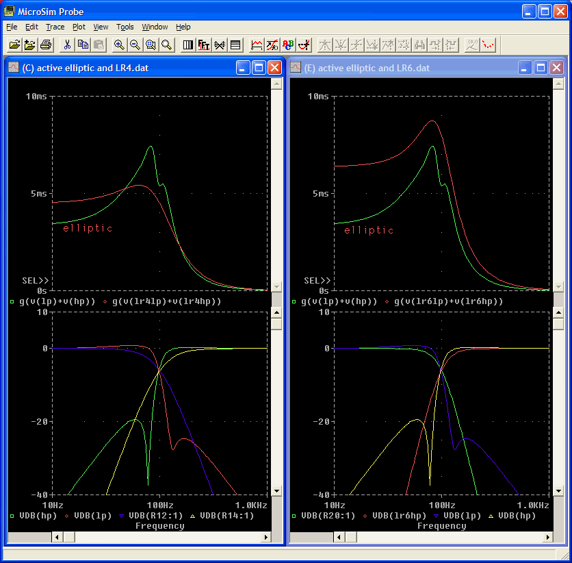
Heheh, could someone update my page and add this comparison of group delay.
Plotted are the magnitude response, and group delays of the summation, comparing my active elliptic, with the LR4 and LR6.
As you can see group delay is better at all frequencies, than the LR6.
It is better than the LR4 at lower frequencies, but has a higher peak just below the crossover ferquency

Plotted are the magnitude response, and group delays of the summation, comparing my active elliptic, with the LR4 and LR6.
As you can see group delay is better at all frequencies, than the LR6.
It is better than the LR4 at lower frequencies, but has a higher peak just below the crossover ferquency
Attachments
Richard's Infinite Slope Filter is not an elliptical filter . I downloaded the patent information several years ago. If one reads here:
http://www.wikipatents.com/US-Patent-7085389/infinite-slope-loudspeaker-crossover-filter/Page-1
One will find that the crossover is a series design that uses autotransformers with a "timing capacitor" tied between the primary and secondary to set the cut off frequency. The slope of the filter is much stronger than most ellipticals (more than 100db).
They *are* elliptic filters.
Modafferi's first passive crossover invention uses a (loosely coupled) transformer and a capacitor for the lopass filter; his invention cleverly uses a transformer instead of 3 inductors. This implements a 3rd order lopass wherein one of the poles is turned into a notch (which is what an elliptic filter is).
I chose to use 2 inductors and 3 capacitors for my lopass because I found it easier to design 2 inductors and wind 'em, than to do trial and error on 1 transformer, to get the coupling coefficient right. My implementation produces a 4th order lopass where one pole is turned into a notch.
Modafferi's 2nd patent (the one you linked) uses a series crossover scheme to reduce the input impedance dip. The potential problem I see with all series crossovers is that during large excursions on the woofer, its resistance at higher frequencies changes. Thus the transfer function to the tweeter is modulated by the woofer's excursion - you get intermodulation distortion. Not sure how audible it would be.
Did your design use the "magnetic brake" associated with coupled windings? Did your design provide a 100 db/octave or more slope? Is the group delay of your elliptical the same as provided by the "infinite slope crossover"?
Clearly, there's a lot more going on with Modaferri's design than you give credit for. High quality autotransformers for audio use are neither common nor inexpensive. Your approach has precious little in common with the infinite slope crossover. If you are serious about achieving a meaningful comparison, try posting detailed amplitude, phase, and group delay data for both designs first - then you can use real evidence to support any claims that Modaferri's crossover has the characteristics of an elliptical. Even the average layman would have to conclude - if Joseph Audio could only obtain the performance of an elliptical crossover using autotransformers - why not simply assemble a third order crossover and add one more reactive component as one would do with a simple, relatively inexpensive elliptical?
Clearly, there's a lot more going on with Modaferri's design than you give credit for. High quality autotransformers for audio use are neither common nor inexpensive. Your approach has precious little in common with the infinite slope crossover. If you are serious about achieving a meaningful comparison, try posting detailed amplitude, phase, and group delay data for both designs first - then you can use real evidence to support any claims that Modaferri's crossover has the characteristics of an elliptical. Even the average layman would have to conclude - if Joseph Audio could only obtain the performance of an elliptical crossover using autotransformers - why not simply assemble a third order crossover and add one more reactive component as one would do with a simple, relatively inexpensive elliptical?
Here you can see some measurements:
Joseph Audio RM22si Signature loudspeaker Measurements part 2 | Stereophile.com
The non-existing vertical lobing is the most interesting part of it. Group-delay distortion is definitley quite high. I.e the woofer semms to be lagging by about 0.5 ms. For the same crossover frequency (2kHz) it would be about half of that with an LR4.
Regards
Charles
fntn,
What I meant by "elliptic", is in the mathematical sense - a class of filters with a notch (pair of zeros) in the transition band. His 1 transformer + capacitor lowpass, clearly implements an elliptic filter. Ditto his hipass.
"Magnetic brake" - sounds like a phrase invented by a marketing guy. Woofers "magnetic brake" constantly, as long as they are driven by a fairly low impedance source.
Transformers with tuned coupling coefficients are something I design all day long. In my day job, I design resonant switching power supplies for high volume production. Modafferi's transformers would be cheaper than using 3 inductors.
Peace out.
Resonant switching power supplies? What's the bandwidth of your "resonant" switching power supplies?
Don't know what transformers you are actually working with - but wideband audio transformers present a very different set of problems from those of power supply transformers. There are only a handful of transformer makers around the globe that specialize in high quality, low distortion, wideband audio transformers. I actually did the legwork more than 5 years ago - contacting individuals in Sweden who hand build these types of transformers. They are anything but inexpensive. Do you know who supplies the autotransformers for Joseph Audio?
Don't know what transformers you are actually working with - but wideband audio transformers present a very different set of problems from those of power supply transformers. There are only a handful of transformer makers around the globe that specialize in high quality, low distortion, wideband audio transformers. I actually did the legwork more than 5 years ago - contacting individuals in Sweden who hand build these types of transformers. They are anything but inexpensive. Do you know who supplies the autotransformers for Joseph Audio?
- Home
- Loudspeakers
- Multi-Way
- Joseph Audio 'Infinite' crossovers.
