I have not seen the circuit, but I can confirm that the AD797 may be very difficult to keep stable for gains lower than some 20dB. It is possible, but additional components are necessary. I hope nobody trying here to use it like UG feedback circuit or with something difficult to drive inside FB loop.
Joshua_G said:Don't you see the benefit of paralleling DACs?
It's off topic, but since it may address another myth, here's my take on this:
Theoretically, paralleling DACs would improve signal-to-noise ratio and linearity. I have seen a few commercial implementations of this concept and in fact, the TI PCM1704 24bit DAC is internaly built as two 23bit DACs in parallel. Unfortunately, the positive effects only scale with SQR(N) where N is the number of parallel devices. Therefore, paralleling 4 1LSB precision DACs will provide a 0.5LSB precision equivalent.
Now, from a practical perspective: paralleling a reasonable number of low end/quality DACs may help linearizing the devices. But for high end devices? It again boils down to the audibility of such an enterprise. Assume an extreme case of 256 paralleled 24bit DACs. Not only will this kind of setup drain perhaps 10A from the power supply and dissipate perhaps hundreds of watts, but the whole design would be impossible to be layed without major issues regarding decoupling and digital lines delays. And for what? For an equivalent 3bit of linearity which for a standard 2V output means 15nV. I can't imagine any opamp able to convert the DAC current output to 15nV precision, so the whole thing is moot.
Finally, any current high end DAC has performances beyond any reasoning to parallel. Look again at the PCM1794A. 132dB dynamic range (Mono), THD+N=0.0004%, S/N=127dB (A-weighted ), 129dB channel separation, etc... I find very strange about GEB (usually highly adverse to THD numbers and any numbers in general) suddenly being concerned about 27bit equivalents, 15 nV precision and distortions in the ppm range. But then, this is just me...
SY said:That doesn't mean it's correct. See figure 42 of the 797 datasheet.
janneman said:As well as figure 41.
Jan Didden
PMA said:I have not seen the circuit, but I can confirm that the AD797 may be very difficult to keep stable for gains lower than some 20dB. It is possible, but additional components are necessary. I hope nobody trying here to use it like UG feedback circuit or with something difficult to drive inside FB loop.
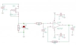
Below is my suggested circuit.
The opamp part is actually used in a well working DAC DIY kit (IC3):
http://www.twistedpearaudio.com/docs/digital/buffalo_schematic.pdf
And here are the DAC's manufacturer application notes (Figure 3):
http://www.esstech.com/PDF/Application_Note_Component_Selection_and_PCB_Layout.pdf
Attachments

syn08 said:
It's off topic, but since it may address another myth, here's my take on this:
Theoretically, paralleling DACs would improve signal-to-noise ratio and linearity. I have seen a few commercial implementations of this concept and in fact, the TI PCM1704 24bit DAC is internaly built as two 23bit DACs in parallel. Unfortunately, the positive effects only scale with SQR(N) where N is the number of parallel devices. Therefore, paralleling 4 1LSB precision DACs will provide a 0.5LSB precision equivalent.
Now, from a practical perspective: paralleling a reasonable number of low end/quality DACs may help linearizing the devices. But for high end devices? It again boils down to the audibility of such an enterprise. Assume an extreme case of 256 paralleled 24bit DACs. Not only will this kind of setup drain perhaps 10A from the power supply and dissipate perhaps hundreds of watts, but the whole design would be impossible to be layed without major issues regarding decoupling and digital lines delays. And for what? For an equivalent 3bit of linearity which for a standard 2V output means 15nV. I can't imagine any opamp able to convert the DAC current output to 15nV precision, so the whole thing is moot.
Finally, any current high end DAC has performances beyond any reasoning to parallel. Look again at the PCM1794A. 132dB dynamic range (Mono), THD+N=0.0004%, S/N=127dB (A-weighted ), 129dB channel separation, etc... I find very strange about GEB (usually highly adverse to THD numbers and any numbers in general) suddenly being concerned about 27bit equivalents, 15 nV precision and distortions in the ppm range. But then, this is just me...
Your reasoning is one thing. The actual audible results as reported by users of this DAC are a different thing. Read this thread:
http://www.diyaudio.com/forums/showthread.php?s=&threadid=128137
Joshua_G said:
Below is my suggested circuit.
Beware of the C6 possible stability problem, it will depend on the C6 value.
Attachments
Joshua_G said:The actual audible results as reported by users of this DAC are a different thing
Ok. Tells us "how it sounds" when you are done

http://www.diyaudio.com/forums/showthread.php?postid=1659347#post1659347
The Buffalo schematic shows a 1u cap on the output. The DAC data sheet shows a 47u. Big difference. Neither is good with a unity gain 797 (if I am to believe the 797's designers), but oscillation is far more likely with 1u than 47u; the latter value will merely bog down the opamp's output and pretty much negate the advantage of using a high performance opamp in that position. You might be able to get away with it sometimes, but it can't be relied on and is poor engineering practice.
I have seen lots of examples of very skilled digital engineers doing very poor analog design (e.g., the bad I/V converters so often used with the old 1541 Philips DACs). This seems to be yet another case. I'm not sure why you think this is an exemplary design. There are far better ways of getting a stable, low noise supply.
I have seen lots of examples of very skilled digital engineers doing very poor analog design (e.g., the bad I/V converters so often used with the old 1541 Philips DACs). This seems to be yet another case. I'm not sure why you think this is an exemplary design. There are far better ways of getting a stable, low noise supply.
janneman said:As well as figure 41.
Jan Didden
I refer you to Fig. 53 a specific. DAC I to V. I built this into an AD1862 eval card and the results were dramatic. The reasoning was that all op-amp's output stages have a rising output impedance at high frequencies (especially the 5532), so clock hash becomes RFI at the input with the normal 1000pF or so directly from inverting input to output. This circuit is a critically damped two pole system. A passive RC at the output can be placed at a fairly high frequency to catch whats left. The op-amp is in a very high noise gain at crossover eliminating most of the design problems.
Of course I took flak for this circuit, but it works.
BTW I found an old buddy on those ESS patents. Small world.
SY said:The Buffalo schematic shows a 1u cap on the output. The DAC data sheet shows a 47u. Big difference. Neither is good with a unity gain 797 (if I am to believe the 797's designers), but oscillation is far more likely with 1u than 47u; the latter value will merely bog down the opamp's output and pretty much negate the advantage of using a high performance opamp in that position. You might be able to get away with it sometimes, but it can't be relied on and is poor engineering practice.
With 47uF, everything is in the hands of God. The result will depend on ESL, ESR, type (SMD/through hole), manufacturer, perhaps even batch.
And then for the price of a Sabre DAC (that is at risk due to possible oscillations) you can get about 100 decent LDO regulators.
scott wurcer said:
I refer you to Fig. 53 a specific. DAC I to V. I built this into an AD1862 eval card and the results were dramatic. The reasoning was that all op-amp's output stages have a rising output impedance at high frequencies (especially the 5532), so clock hash becomes RFI at the input with the normal 1000pF or so directly from inverting input to output. This circuit is a critically damped two pole system. A passive RC at the output can be placed at a fairly high frequency to catch whats left. The op-amp is in a very high noise gain at crossover eliminating most of the design problems.
Of course I took flak for this circuit, but it works.
BTW I found an old buddy on those ESS patents. Small world.
Scott,
I have used that circuit also, but it can only be used with DACs that have a bipolar Iout. Earlier DAC models for instance from Philips had an unipolar Iout (like 0 > 2mA) and than that cap just makes it an integrator which drifts up to the ceiling.
Jan Didden
scott wurcer said:I refer you to Fig. 53 a specific. DAC I to V. I built this into an AD1862 eval card and the results were dramatic. The reasoning was that all op-amp's output stages have a rising output impedance at high frequencies (especially the 5532), so clock hash becomes RFI at the input with the normal 1000pF or so directly from inverting input to output. This circuit is a critically damped two pole system. A passive RC at the output can be placed at a fairly high frequency to catch whats left. The op-amp is in a very high noise gain at crossover eliminating most of the design problems.
Scott,
You are such an engineer

http://www.diyaudio.com/forums/showthread.php?postid=1711175#post1711175
SY said:The Buffalo schematic shows a 1u cap on the output. The DAC data sheet shows a 47u. Big difference. Neither is good with a unity gain 797 (if I am to believe the 797's designers), but oscillation is far more likely with 1u than 47u; the latter value will merely bog down the opamp's output and pretty much negate the advantage of using a high performance opamp in that position. You might be able to get away with it sometimes, but it can't be relied on and is poor engineering practice.
Correct points, but I make no definitive comments. The 120 Ohm snubber and large output cap might in fact be always stable. Again no one would have envisioned an application like this.
-Syn08, the ESS people seem to be actively courting the GEB it's not my place to comment.
syn08 said:
Scott,
You are such an engineer
http://www.diyaudio.com/forums/showthread.php?postid=1711175#post1711175
Well, the details are left to the designer.
regulated output stages?
May I disturb the peace for a moment and ask about your opinion?
In preamp or power amp frontends regulated power supplies are pretty standard, there seems to be even some sort of competition currently to see who is able to build the most complex discrete regulator.
But what about regulating the output stage?
Forget for a moment power dissipation and lack of integrated regulators (only LT1083 comes to mind), what are your thoughts about this?
I'm specifically talking about regulators with massive capacitance infront and after the regulator (say 10000-20000uF infront, about 1000uF afterwards), so not to use it as cap-replacement.*
In my opinion this yields ripplefree rails even at full output, yet no huge cap banks that stress diodes and send back EMF. Should also be good for linearity as the usual output stage is a follower that is not very strong PSRR-wise.
Thoughts?
Have fun, Hannes
*The 1000uF to improve transient response after the regulator, the large capacitance infront of the regulator reduces ripple to a level that already several volts drop-out voltage are sufficient (keep power dissipation down).
- Status
- Not open for further replies.
- Home
- Amplifiers
- Solid State
- John Curl's Blowtorch preamplifier