What John Curl said, over and over. Our company built amps and preamps which used boatloads of the biggest C0Gs around. That would be 0.1uF@50V or 0.047uF@100V. *Fortunately,* the V limit doubles below 70deg C ambient. Our top preamp, which was indeed spectacular, contained 2 coupling caps per ch made from 120 C0Gs (84 for a 4uF@200V and 40 for 4uF@100V) built as ladders. Sonically, they make polystyrene, et al cry for Mama. Now that was around $400 per side for just those parts. Worth every penny. You need to avoid magnetic leads, and nobody tells you which ones don't have 'em...X7Rs actually kick *** too for audio, if you address microphonics.
john curl said:Listening tests.
The usual escape pod

john curl said:
About 25 years ago, and before, I happily used tantalum bypass caps with values of 47uf to 150uf. I still have 100's of them available to me.
Doing an A-B test with my early Vendetta SCP-1 about 25 years ago, I clearly heard a difference between the 150uf tantalum caps and 8uf polypropylene caps in the power supply bypass.
What a drag! I had to redesign both the case and the power supply buffers to get it to sound its best. I would not have done it on a whim.
Now, IF anyone can make a perfectly good audio preamp that sounds as good as anything out there with ceramic or tantalum bypass caps, well good for them. It might be that IC's with their superior power supply rejection, will tolerate nonlinear caps in the power supply bypass. I hope so.
Hundreds of uF tantalum caps for bypass? What am I missing here? Such would cost $30 a pop today. And why would anyone use such values AND tantalum for bypass? If you are talking about bypassing the PS output, this is different to bypassing at the power supply terminals of the devices. I thought you need something to bypass the power pins of the AD797 (always a very good practice).
Given the quality of tantalum caps today (and probably worse 25 years ago), coupled with a poor PSRR of the amp itself, it could theoretically make an audible difference. However, multilayer ceramics are in a completely different league when it comes to non-linearities.
0.1uF is indeed a common value for decoupling and I would suggest ceramic, even if it's not the most linear on the planet, for the low parasitic inductance. If it would be to chose between a multilayer Y5V ceramic with virtually zero series inductance and a big fat 0.1uF ultralinear polyprop with measurable series inductance which one would you chose as a bypass?
0.1uF is the standard bypass value, nobody is debating this.
Could you elaborate on that?You need to avoid magnetic leads,
Sam Lord said:What John Curl said, over and over. Our company built amps and preamps which used boatloads of the biggest C0Gs around. That would be 0.1uF@50V or 0.047uF@100V. *Fortunately,* the V limit doubles below 70deg C ambient. Our top preamp, which was indeed spectacular, contained 2 coupling caps per ch made from 120 C0Gs (84 for a 4uF@200V and 40 for 4uF@100V) built as ladders. Sonically, they make polystyrene, et al cry for Mama. Now that was around $400 per side for just those parts. Worth every penny. You need to avoid magnetic leads, and nobody tells you which ones don't have 'em...X7Rs actually kick *** too for audio, if you address microphonics.
I thought John said ceramic is bad
Which preamp model is this? Paralleling caps is always a good idea, it decreases the series inductance. About audibility of such a setup... I pass
C0Gs = monolythic ceramic with great temp stability and almost no piezoelectric properties. Also higher Vmax than tantalum. Re. leads as well as usefulness of X7Rs, these are my opinions only. I can say we never saw any ringing from X7R ladders in our gear. The company is defunct, Essence Electro Acoustics, best known for very high-end speakers with individual driver enclosures in its loudspeakers since circa 1979.syn08 said:I thought John said ceramic is bad
Which preamp model is this? Paralleling caps is always a good idea, it decreases the series inductance. About audibility of such a setup... I pass
syn08 said:a) Why should a bypass cap be (ultra)linear?
I am not a high end audio designer. I don't even play one on TV. I am sure that the people who toil in the high end audio design realm are pleased to hear that.
However, almost every amplifier I have ever seen (please note that is almost) has the bypass caps directly in the audio path. A simple nodal analysis shows this.
Could someone please explain to me what I am missing? (NOT directed specifically at syn08...)
CG said:
However, almost every amplifier I have ever seen (please note that is almost) has the bypass caps directly in the audio path. A simple nodal analysis shows this.
Could someone please explain to me what I am missing? (NOT directed specifically at syn08...)
I'll give it a shot if you could explain what you mean by "has the bypass caps directly in the audio path".
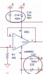
This is what I mean by bypass. Why should the 100n cap be ultra-linear?
Attachments
I'll give it a shot if you could explain what you mean by "has the bypass caps directly in the audio path".
The clue: "What's inside that triangle?" Think about where the return currents have to flow and where the currents to each stage come from.
SY said:
The clue: "What's inside that triangle?" Think about where the return currents have to flow and where the currents to each stage come from.
This is the PSRR discussion. Every nonlinearity/distortion/noise/you name it/ at the supply pins reflects to the output attenuated by the PSRR. I am having a hard time believing that the output of an AD797 can reflect any measurable and/or audible nonlinearity of the bypass cap.
AD797 has a PSRR- 130dB @ 100Hz and 60dB @ 100KHz Roughly speaking, the cap distortion has to be worse than 1% @ 100KHz to have an output effect comparable with the opamp itself. Now somebody show me a ceramic cap for electronic use with 1% distortions/nonlinearities.
The PGP amp has an overall PSRR of about 60dB, doesn't use any opamps in the signal path, is build with multilayer bypass caps only and reached under 1ppm distortions.
syn08 said:I'll give it a shot if you could explain what you mean by "has the bypass caps directly in the audio path".
What everybody is calling the bypass caps are connected between the power supplies and "ground" or common.
The load is connected between the opamp output and common. The current for the load has to pass through something to return to the amplifier. Otherwise the output current would be zero. Here it looks to me like the load current passes through the bypass caps and whatever the path is in the power supply.
The same argument can be made with regard to the input.
I don't see any pins on this opamp named "common" or "ground."
To many people ground is ground, some magical node that represents the electric equivalent of absolute zero.
John and any other low level analog designer know that this is just not true. It's worse than some signal leads because both the power and signal currents flow there (and so do ripple and noise currents from those ever so standard op-amp bypass caps). All these get mixed together and a node analysis will show that without the most meticulous attention to detail, these errors can appear as an input signal to the stage
Yes the errors are small, but John has revealed that good pre-amp design needs better than 100dB signal cleanliness.
lumanauw said:What's the mechanism that make we need to put bypass cap close to the IC?
PCB traces impedance, a potential source of HF instability.
hermanv said:To many people ground is ground, some magical node that represents the electric equivalent of absolute zero.
Nobody is debating the need for bypass caps. What is debated is the effect of the bypass cap linearity on the IC (AD797) output signal.
Do yourself a favour and perform what you call "a node analysis". It will be an interesting and relevant exercise in understanding how opamps work and what are the error sources.
Yah hermanv, the ground design sure separates great design from good (necessary, not sufficient). Syn08, sorry I repeated stuff you already knew. The caps I mentioned were coupling caps, kinda OT for this discussion. Guido Tent's layout paper at Hypex is a nice resource. Thanks all, wonderful thread.
There are several reasons for power supply bypassing but the original one, and probably still the most important one is stability. If the supply isn't bypassed effectively the opamp or discrete circuit can oscillate. Even an emitter follower can oscillate if the supply and the load and the source aren't managed carefully. With fast parts its even more of an issue. A 500 MHz opamp will oscillate like crazy if the layout isn't just right. And with a 500 MHz GBW its very possible that you won't see the oscillation until you hook it to a sampling scope. The self resonance of the bypassing system becomes important- if its below the unity gain crossover it can contribute to oscillation.lumanauw said:What's the mechanism that make we need to put bypass cap close to the IC?
Its possible to model the supply bypasses and the filter caps as being in series with the load so the linearity of the power system becomes important. How important depends. I have heard the differences but can't point to the exact mechanism. I just use a matrix of parts so its all OK.
- Status
- Not open for further replies.
- Home
- Amplifiers
- Solid State
- John Curl's Blowtorch preamplifier