The reason for the lack of high speed rectifier bridges is that they are targeted at switching supplies. And most switchers use architectures that aren't compatible with bridges. The radiated field is the big problem and the faster the rate of change the bigger the field for the same energy. Faster diodes help but looking at the whole problem is important. Make the "windows" smaller. Look at the fields with a probe and see where they are. The fields are on both sides of the rectifier. And don't think that the transformer will block it from going back up the line. Also bigger filter caps may make the situation much worse. As the 'conduction angle shrinks the peak currents go up. Its possible that an LC network around the diode would improve things. Using power fets as controlled turn on switches switches may be an effective solution.
I have often used 1/2 wave rectifiers. it has solved some practical problems and can work just fine. I used it to take a single pair of wires from a transformer (wall wart etc.) and make a full split supply. The traditional engineers usually are reluctant to believe it can work. I would not use it for a power amp but for a preamp it may be fine.
I found that an easy and cheap method to circumvent (or eliminate, just a matter of definition) the problem is to use series resistors with each of the four terminals of a bridge (in lieu of direct access for a true series connection), making it "softer" (and in fact it adds damping resistance to the tank circuit). This makes only sense with low power requirements, of course, otherwise only good diodes and/or proper snubbering are an option (I think most of us will know this article on PSU diode snubbers).1audio said:Some think that a small RC network across the individual diodes works much the same, but I prefer to eliminate the problem from the source, rather than attempt to fix it after I know that it has occurred, so I will stick to high speed, soft recovery diodes for my best efforts.
Still I also had to modfiy some smaller active speakers which had this ringing problem to a large extent (very gritty sound, took me a while to track it down to the supply), from it's "textbook" power supply, consisting of a toroid + standard bridge + low-ESR caps -- sort of the worst-case scenario, it seems. Additionally to the damping resistors I also added a second RC stage after this first -- in fact I started with that but wasn't fully successfull since some of the disturbance came from dircect radiation and/or feedtrough via the mains line, to other devices feeding the speakers. The slightly lesser max continuous power headroom was fully worth the overall increase in sound quality, and the peak power output didn't change notably, anyway.
EDIT: I have a signature in another forum that reads "every PSU is a switching PSU".... took me some years to figure out hoe true this really is...
- Klaus
by JC not 1ajohn curl said:...........so I will stick to high speed, soft recovery diodes for my best efforts.
1audio said:
That is the pot we used in the production Spectral DMC-10. It had the best sound of the practical options at the time. We used a 10K pot to keep the frequency effects at a minimum. Lower would be better but would induce (more) distortion in tube sources. We tried to keep the wiper load as high as possible to reduce distortions, errors and wiper noise to a minimum.
Try running a 10-20 meg (to start) resistor across the outers to the center wiper.
It's the same issue as the diode, in essence. It's a dynamic 'slap back' issue, with regards to the generation itself, on top of the pot being an uncontrolled variable in otherwise stable situation. A tuned bleed off can do wonders, while still preserving the dynamic and micro-structural envelope. Find the balance that works for that particular loading scenario. I know it sounds weird, but give it a go. It's the dynamic, or complex peak values that are giving the whole thing the fits. I know you know this already - but it's a good place to play with damping. You tend to end up with less of that 'tonal change/balance' issue as you advance through wiper positions.

Jackinnj show us a sim and measurement result about RC accross dioda.
http://www.diyaudio.com/forums/showthread.php?s=&threadid=56106&perpage=25&highlight=&pagenumber=19
http://www.diyaudio.com/forums/showthread.php?s=&threadid=56106&perpage=25&highlight=&pagenumber=19
lumanauw:
The app notes refer to specific issues in switching amps and power supplies using power FETs. I think this gives a better idea of the issue in a 60 Hz power supply: Fast Rectifier
KBK:
If I didn't know better I would describe your note as first order audiophile gobbledygook. But I do know a little better. I have had no success with those tricks myself but I suspect they may help, I'm not sure how. Does the pot material, wiper allow etc. make a difference with this trick? I abandoned the pots in premium products a long time ago and used Tech Labs switches with Vishay resistors. Nothing else I tried came close. I went on to look at more exotic things like airtight enclosures of non-magnetic non-conductive materials and vibration damping tricks.
By using a soft recovery diode instead of the MUR diode, one can skip the RC network.
I prefer to use soft recovery diodes (Stealth and MSR types) or Schottky diodes. Some seem not to like the sound from Schottky diodes but I have not
heard anything bad about soft recovery diodes.
Sigurd
I prefer to use soft recovery diodes (Stealth and MSR types) or Schottky diodes. Some seem not to like the sound from Schottky diodes but I have not
heard anything bad about soft recovery diodes.
Sigurd
lumanauw said:Jackinnj show us a sim and measurement result about RC accross dioda.
http://www.diyaudio.com/forums/showthread.php?s=&threadid=56106&perpage=25&highlight=&pagenumber=19
john curl said:[B
.....
I started to research the problem at this time, especially encouraged by a friend of mine, Rick Miller, who tested different diodes with an RF spectrum analyzer and published it in TAA back in the early 90's. I found that with a CURRENT PROBE that I could capture the current coming from the rectifier bridge, and it was much easier to see the problem. I had not owned a current probe previously, so I was not easily able to make this measurement, but it was obvious, once I did. .... [/B]
This shows that audible problems may exist even if one can not measure them. They are just waiting for the correct measuring tool or method to be used or invented.
RK
1audio said:I have often used 1/2 wave rectifiers. it has solved some practical problems and can work just fine. I used it to take a single pair of wires from a transformer (wall wart etc.) and make a full split supply. The traditional engineers usually are reluctant to believe it can work. I would not use it for a power amp but for a preamp it may be fine.
This can work fairly well, but you need larger bulk filter caps because the ripple is 60 Hz not 120 Hz as with a FW rectifier. You also need to have balanced +/- loading, because technically this circuit is actually a form of voltage multiplier. Unbalance the load too much and you could end up with one of the rails non-existent or even reversed (following the ac waveform), might damage a semiconductor this way.
I recently modified several Fluke 8050A DMMs to eliminate the battery charger circuit. It's hard to find the battery packs anymore, and the DMM won't work at all if the nominal 4.8 vdc battery falls below 4 vdc or so, even with the ac power connected. The battery version uses a lower secondary voltage power transformer, so I used the 1/2 wave rectification method to get sufficient supply dc voltage for the 10v linear regulator IC. I found the processor and display did not always come on, and I had to add some "watt-waster" resistive load to balance the supply currents and get the DMM to start up properly.
1audio said:The reason for the lack of high speed rectifier bridges is that they are targeted at switching supplies. And most switchers use architectures that aren't compatible with bridges. The radiated field is the big problem and the faster the rate of change the bigger the field for the same energy. Faster diodes help but looking at the whole problem is important. Make the "windows" smaller. Look at the fields with a probe and see where they are. The fields are on both sides of the rectifier. And don't think that the transformer will block it from going back up the line. Also bigger filter caps may make the situation much worse. As the 'conduction angle shrinks the peak currents go up. Its possible that an LC network around the diode would improve things. Using power fets as controlled turn on switches switches may be an effective solution.
Yes, the use of MOSFETs for rectification *does* work, using synchronous rectification. We do that with high-power dc converters, using Schottky rectifiers (or the MOSFET body diode) for the initial forward conduction. Then we turn on the MOSFET with its low on-resistance to reduce power dissipation. You have to monitor the voltage drop and polarity across the MOSFET to know when to turn it off. By adjusting the turn-off time/slope you can really reduce the EMI produced by rectification. But the gate control and shoot-through protection overhead is pretty expensive. I don't know that it would be worth the cost or if it would much more effective with 50/60Hz power lines than discrete fast soft-recovery diodes and a faraday shield in the transformer.
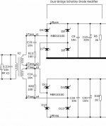
I also like this arrangement pretty much, as it allows for various forms of symmetry and separation, use of lower diode breakdown voltages etc.Sigurd Ruschkow said:John,
the last 5 years I have started to use only dual bridge rectifier schemes (ie 8 discrete diodes to make a dual voltage supply).
I like the way it creates an "active" ground. See attachment.
Any thoughs on this?
There might be one noise penalty, though... (I haven't measured this in detail so far, so it's only armchair reasoning) :
When the diodes don't conduct, most of the cycle in fact, the xformer leakage capacitance is seriesed with the diodes' capacitances, while when the diodes conduct the xformer is connected directly. This represents a "chopped" total leakage capacitance that might further "chop up" GND currents to/from other gear. With the simple bridge the coupling capacitance is always in place and doesn't change that much (but still to some extent), which might give way more benign GND-current spectra.
- Klaus
I also use the dual bridge diode array, also. The A mod for the Vendetta Research phono stage was just this. Later, I also upgraded to high speed, soft recovery diodes, and this was called the D mod. It is not a universal fix however, since the +/- loads must be matched.
- Status
- Not open for further replies.
- Home
- Amplifiers
- Solid State
- John Curl's Blowtorch preamplifier