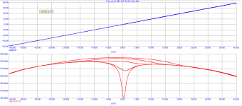
To revisit the 'optimum" bias point, I ran a purely mathematical exercise. I think I know the one I want. This is simply the complementary follower by itself.
THD vs. bias, ideal devices, 0.22 Ohm degeneration, 8 Ohm load
Watts out .1 1 10 100
THD 500mA .0005% .005% .11% .11%
THD 100mA .013% .045% .03% .04%
Numbers are not very interesting itself. I think you (and few others) are smart enough to decipher the attached plots. Bias current per pair 6, 23, 65, 143, 237mA. And please do not analyze 8ohms (I did so as well to be on same track), no speaker is that light load.
Attachments
Last edited:
Vacuum valves, with all of their well understood limitations, do have one seldom praised advantage - they don't mind running very hot. I wonder what actual listening SPL readers and writers of this thread would measure in their homes, at their normal listening levels.
Then, knowing their speakers' nominal sensitivity, they could ballpark their own amplifiers "0VU" and peak output levels, and estimate the required power for, say, -50dBVU or -60dBVU. This is important territory musically, surely. And don't call me Shirley.
The numbers are so small that conventional measurements are difficult, but is the current state of modeling good enough to calculate? For example, PMA's transconductance curves to another several decades lower?
Much thanks, as always,
Chris
The bipolar Stasis amplifiers from '78 to '92 had an optimum bias point
where it measured the lowest distortion, but all agreed it sounded better
with more bias, and that's how they shipped.
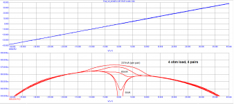
4 pairs, 4 ohm load (realistic load!). This is what counts in creating high harmonics, not numbers. That's why there was a tail. 0R22 per one Re.
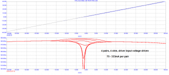
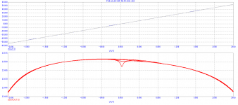
The next one shows output stage transfer function in case that the driver transistors are voltage driven (previous examples were through 3k to imitate VAS output impedance). What would be better sounding, the deep notch, or mild hill? I think we know what spectra belong to them. The only tool that fights against the underbiased output is the strong feedback. Analyze transfer functions and output impedance nonlinearity, even with the feedback, residuals are still there. That's why class A is the best.
Attachments
Complete amp transfer function. THD numbers almost do not differ, spectra are from fast decay of high order harmonics to the long tailed, forest of harmonics. This is re idea "low bias, just behind the point where crossover distortion disappears". In no setting of those used there will be any visible crossover distortion.
Attachments
Do a bias vs thd plot.
THx-RNMarsh
Your request is undefined.
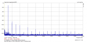
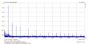
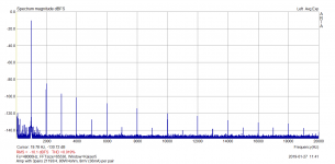
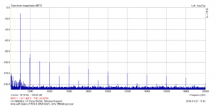
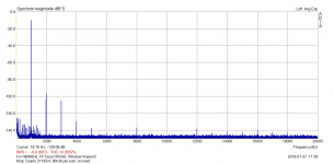
Real amplifier, measurements (not simulation), 80W/4ohm test power
- 3 pairs 21193/4
- 0R22 Re resistors
- 18mA, 36mA, 82mA and 112mA idle current per pair
See that THD number is always almost the same, however spectra do differ, the lower bias, the higher amplitude of high order harmonics. The 112mA is about optimum, but in the wide range starting from 80mA the result is OK. High order harmonics are below -120dBr to the fundamental.. No problem to keep the idle current.
Attachments
Last edited:
Numbers are not very interesting itself. I think you (and few others) are smart enough to decipher the attached plots. Bias current per pair 6, 23, 65, 143, 237mA. And please do not analyze 8ohms (I did so as well to be on same track), no speaker is that light load.
Are all these tests into pure resistance?
Jn
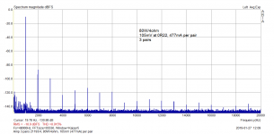
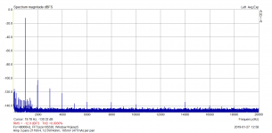
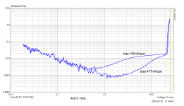
477mA/pair vs. 100mA/pair
Thanks for all the work Pavel. Many of your plots show dominant seconds which has nothing to do with optimum bias but PNP/NPN match. I only wanted to show that turning up the bias gave "First Watt" behavior at low power, very low THD that monotonically decreases from 10W to 0 where most of the (unmasked) listening occurs. The ripples in THD vs level that you get when you tune up the optimum point, if you examine carefully, both go up and down but also flip harmonic structure around.
THD at full power is not very interesting, neither are plots of THD+noise since all useful information at low power is obscured. After all this is how everyone hid their crossover distortion for decades.
It's different with MOSFET's.
Snip
So tonight with a glass of port we will listen to an LP and we will enjoy the experience.
Plus you are getting plenty of exercise, jumping up every 20 mins to lift, flip,dust and lower and then retrieving another album.
My Cd's are slowly getting converted to mp3 files on my tablet and with Bluetooth all my music is available with a swipe without leaving my chair.
Strange that Bluetooth is not discussed too much around here, yet new amplifiers are being offered with this feature?
Pavel is right about what we try to do to lower output stage distortion. There is another variable in the equation and that is the VALUE of the EMITTER Resistor. Pavel is using 0.22 ohms, and that is a popular value, but I have used 0.12 to 0.33 ohms with Parasound amps, and even as low as 0.05 ohms in other (Class AB1) designs.
With 0.22 ohms, then about 100ma is close to perfect for a transistor output stage, and it would measure 0.22mV across one emitter resistor. I originally stated that a voltage drop of 0.15mv-to perhaps 0.25mV is tolerable. An even higher voltage drop, like 0.33 mV might be OK, IF the heatsink can support it, but usually they can't. Overbiasing, for sonic quality, (and lowest higher order harmonic distortion) is much better than underbiasing (less than 12mV or so). I call it a speed bump, is better than a pothole in the transfer function. However, IF the heatsink will not support the optimum current because it gets too hot, (over 50 degrees C) then increasing the size of the emitter resistor, should work better, than the nominal 0.22 ohm, even though it might have to be a special order by the manufacturer, and they will tend to resist it. Usually what we normally do is increase the number of paralleled pairs on the output, so while the A-21 uses 4 output pairs, the new JC-5 uses 6 output pairs, and the soon to come JC-1+ uses 12 output pairs with 0.22 ohm resistors. The present JC-1 has 9 output pairs, BUT it uses 0.18 ohms instead, so that the optimum current of each pair can be increased. Smaller and cheaper power amps might be better off with 0.27, or even 0.33 ohms, to keep the transfer from Class A (there is almost always some) to Class B as smooth as possible.
With 0.22 ohms, then about 100ma is close to perfect for a transistor output stage, and it would measure 0.22mV across one emitter resistor. I originally stated that a voltage drop of 0.15mv-to perhaps 0.25mV is tolerable. An even higher voltage drop, like 0.33 mV might be OK, IF the heatsink can support it, but usually they can't. Overbiasing, for sonic quality, (and lowest higher order harmonic distortion) is much better than underbiasing (less than 12mV or so). I call it a speed bump, is better than a pothole in the transfer function. However, IF the heatsink will not support the optimum current because it gets too hot, (over 50 degrees C) then increasing the size of the emitter resistor, should work better, than the nominal 0.22 ohm, even though it might have to be a special order by the manufacturer, and they will tend to resist it. Usually what we normally do is increase the number of paralleled pairs on the output, so while the A-21 uses 4 output pairs, the new JC-5 uses 6 output pairs, and the soon to come JC-1+ uses 12 output pairs with 0.22 ohm resistors. The present JC-1 has 9 output pairs, BUT it uses 0.18 ohms instead, so that the optimum current of each pair can be increased. Smaller and cheaper power amps might be better off with 0.27, or even 0.33 ohms, to keep the transfer from Class A (there is almost always some) to Class B as smooth as possible.
Last edited:
- Status
- Not open for further replies.
- Home
- Member Areas
- The Lounge
- John Curl's Blowtorch preamplifier part III