Yes....and audible on Youtube too.Of course if you listen to JC's or Nelson/Wayne's designs they sound significantly better than the mass marketed mid-fi stuff.
Yes, the must have but how to implement, lol.One of the issues is the volume control, remote control.
3dB, sure thing.Step size used to bother me on some older attenuators that did 3 dB step size as everyone also "knows" that is the minimum perceptable change.
I currently run a Denon amp with electronic volume control in 0.5dB steps, and this step size is perfectly audible.So one set of experiments that I will do by my ears only will be on step size. A simple set up with far more taps than needed and a bit of listening to changing the volume sound give me a hint as to what I want/where.
This precision is not required, but it is nice to be able to bump up/down by 0.5dB quite often.
I bought some little orange (Panasonic ?) bistable signal relays for purpose of exploring this question, the coil current gets replaced by permanent magnets, maybe a difference......in a box somewhere, I never got around to trying them.Where I think even those fall short is in the armature structure and how close the signal conductors come to the magnetic structure. So that is one of the items I will try to see if it shows up in the measurements.
Haha.Cellphone input ted so expect typos.
Dan.
Of course if you listen to JC's or Nelson/Wayne's designs they sound significantly better than the mass marketed mid-fi stuff.
There are some simple reasons like that IEC standards that seem to have been influenced by high volume manufacturers call for minimum loudspeaker impedance to be 80% of rated impedance. Or in simply terms a mass market mid-fi audio power amplifier will sound nasty if your loudspeaker impedance drops below 6 ohms. As the AES standard for many years was 50% and many folks would put two loudspeakers on one channel most better gear can drive 2 ohms or even less. As some high end loudspeakers may drop even lower they would sound less than their best on amplifiers that could only hand loads above 6 ohms.
Then there are many other issues such as handling the ever worsening EMI environment.
On a different subject I spoke to JC about building a preamp. One of the issues is the volume control. It seems the future will be relay bank types for high end use to allow remote control and avoid limited production parts.
Obviously relay banks can get better channel matching and more precise steps. One of the issues that pops up is number of steps and step size. As everyone "knows" step size should be logarithmic. Of course cheap controls have about 45 dB of range and then a bit more sharp attenuation below that. Partly because tracking really falls apart at the low levels.
What is of interest is that human hearing (exempting some here by their claims and results) tends to compress the log scale theory above 70 dB ish and below 25 dB ish.
Step size used to bother me on some older attenuators that did 3 dB step size as everyone also "knows" that is the minimum perceptable change. Simple engineering common sense would set the step size below that number. Of course my experience is that 3 dB is not always 3 dB depending on sound pressure level.
So one set of experiments that I will do by my ears only will be on step size. A simple set up with far more taps than needed and a bit of listening to changing the volume sound give me a hint as to what I want/where.
Now by measurement my first step is to select the relays. So I ordered one of each that seemed to be designed for such use from both Mouser and Digikey. If any readers of this nonsense care to suggest particular units and where to get them I am open to suggestions. (Wayne - hint!)
Of some interest except to Scott who doesn't believe there can be discontinuities in the output voltage through a switch, most of the relays use gold plated crossbar switches. Where I think even those fall short is in the armature structure and how close the signal conductors come to the magnetic structure. So that is one of the items I will try to see if it shows up in the measurements.
Another issue is of course thermoelectric potential.
Now JC prefers the TO5 can RF relays and interestingly enough they do avoid much of the armature issues. A minor issue is that where all the other relays being tested are unt $5.00 the TO5 ones are $78.00 and only about 10 units are in stock!
My test relays are 12 volt versions with PC pins. I suspect for the fun of it I will compare Omrons G6 types with gull wings to the pinned version as I have both. Panasonic seems to have more options including one that has a maximum switch current rating of .01 amperes.
Cellphone input ted so expect typos.
Try Kemet EC2 or EA2 (formerly NEC Tokin parts)
Of some interest except to Scott who doesn't believe there can be discontinuities in the output voltage through a switch, most of the relays use gold plated crossbar switches. Where I think even those fall short is in the armature structure and how close the signal conductors come to the magnetic structure. So that is one of the items I will try to see if it shows up in the measurements.
.
Talk is cheap, discontinuities = gross IMD = cell phone base stations don't work. I await any actual data.
Oh and I forgot we use them by the 1000's in automated test equipment, nothing to report here either. Or maybe you want to take a look at the Tek reed relay settling time reference generator. In fact with the Tek reed pulse generator you can observe the mercury wicking causing a momentary increase in contact resistance until it suddenly breaks the break can generate 25psec edges, this was used even in 1963. No discontinuities sorry to disappoint. Relays bounce of course but you knew that.
Last edited:
Of course if you listen to JC's or Nelson/Wayne's designs they sound significantly better than the mass marketed mid-fi stuff.
That's a funny thing to say, many of Nelson's projects reject obeisance to things like THD, etc. In all due respect I have no problem with this in fact recently I find this process more fun and entertaining and am working on an open loop auto-transformer as gain amplifier along similar lines. IME these circuits have clear colorations and are not by strict definition "accurate".
Talk is cheap, discontinuities = gross IMD = cell phone base stations don't work. I await any actual data.
Oh and I forgot we use them by the 1000's in automated test equipment, nothing to report here either. Or maybe you want to take a look at the Tek reed relay settling time reference generator. In fact with the Tek reed pulse generator you can observe the mercury wicking causing a momentary increase in contact resistance until it suddenly breaks the break can generate 25psec edges, this was used even in 1963. No discontinuities sorry to disappoint. Relays bounce of course but you knew that.
I have one of those and it still works. Possibly the only way to get 25 pS at 25V. I may need to tune it the next time I fire it up.
I would be happy to send 1 or 2 TO5 can relays to Ed. But that's possibly "poisoning the well" for any others. The Shibasoku uses shielded relays from this family: 水銀リレー/HFW | 製品カタログ | 株式会社 沖田製作所 They work well but I have had to replace several. One could argue that reed relays must have problems since the signal must go through a magnetic field.
You can make the volume taper as fine as you want with enough relays. 8 relays will give 128 dB range with .5 dB resolution and software can allow you to taper it however you want. I would make the taper dynamic depending on the current position of the control with the resolution getting coarser with the magnitude of the change.
The old stepped switches were limited mechanically and cost. You could get 48 step 1 dB pots which would be in a disk mastering chain. The 3 dB 16 step ones were for things like radio station mixers.
I found a good relay control package with software years ago. The guy gave me his complete package (including software) which I have somewhere. I built one and it worked well enough that I have not been able to get it back after lending it out years ago. Today fresh software on a current platform would be the only way to go. (Arduino or Raspberry Pi anyone?) I know where those solutions may be available as well.
> One could argue that reed relays must have problems since the signal must go through a magnetic field.
Linear Audio | your tech audio resource
Patrick
Linear Audio | your tech audio resource
Patrick
In fact with the Tek reed pulse generator you can observe the mercury wicking causing a momentary increase in contact resistance until it suddenly breaks the break can generate 25psec edges, this was used even in 1963. No discontinuities sorry to disappoint. Relays bounce of course but you knew that.
Interesting.... I didnt think anyone remembered such relays. the mercury wetted relay contact was used for high current/voltage connect/disconnect to prevent contact arcing and damaging the contacts...... very long life....maybe telecom used. But guess what? A few months ago, I was looking for my capacitor DA tester... guess i loaned it and it never was returned. So, i bought another mercury wetted contact relay to make another DA tester and they still make them !! They are in a metal hermetically sealed octal tube base.
Good for high voltage pulse generators with fast, clean break. Replaced in large part by using certain transistors into avalanche mode. Very fast. And, replaced due to health hazard. I guess it is still available for repair/service or HV application use. ??
THx-RNMarsh
Hi John, thanks, interesting/curious.
Jack's new gizmo doesn't worry me in the slightest, my form is totally different, (coating, putty, potable, moulded, extrudable, 3D printable etc) and able to be implemented anywhere in systems and without electrical series connection.....and foremost economical/affordable and not unobtainium.
The effect at first order is to 'clarify' the system sound, but that gets boring because it exposes power, cables, system components and transducers, ruthlessly.
The second order effect is to deliberately add known 'dirt' back in....this is where the 'goove', the 'vibe', the peace and the fun happens lol.
Tone control ?....yes, but so is every cable, system component and transducer already in existence, however the system resultant is not perfectly predictable because some materials 'play nice', some don't.
Add to this signal incorporated noise and signal driven system noise dependence and the result is a crapshoot.......filtering system energy inputs and energy outputs changes everything, subjectively at least.
I might even get around to properly attempting to capture system differences soon now that I'm pretty satisfied with what I have now....this has been a long road.
Dan.
OT. -> Studio Effects section of the forum.
//
The future of hifi is digital audio, and volume control is by dsp, not relays. The dsp function can be matched to ear response if you want. In fact it's easy to use the system to measure the customers ear response and tailor the volume control to match. This is actually done in some headphone systems already.
That's a funny thing to say, many of Nelson's projects reject obeisance to things like THD, etc. In all due respect I have no problem with this in fact recently I find this process more fun and entertaining and am working on an open loop auto-transformer as gain amplifier along similar lines. IME these circuits have clear colorations and are not by strict definition "accurate".
Although it is easy to chase THD down to trivial levels time after time it has been researched to show below easily measured levels perception-wise it is not an issue. Some hold the theory it you push THD down you also reduce other artifacts.
As to relays if there is no contact issue why are there gold crossbar bifurcated relays or for higher current use mercury wetted ones? On some small enclosed relays there is a small tab intended to be broken off after soldering and cleaning. That makes sure air can circulate into the case. Why?
Last edited:
I'm also contemplating a preamp and using relays, for the mundane reasons that they simplify the mechanical assembly of the front panel, avoid the purchase of 60-step rotary switches, and dispense with any possible need for shaft extenders, U-joint couplers, etc. Just a rotary encoder (or a pair of pushbuttons! Volume_Up, Volume_Down) on the panel, and a noise-immune 4 wire flat cable that snakes back to where the guts are located.
With 7 relays you can get very fine grained steps; I happen to like Mark Levinson's idea of offering 100 different volume levels numbered 0-99; it fits nicely on a 2 digit display. If you use 14 SPDT relays instead of 7 DPDT relays, you can also get a very sensitive Balance control, via software modifications.
And of course it dramatically simplifies remote control of volume.
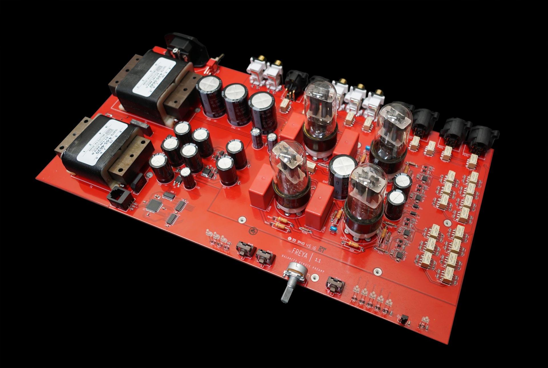
Methinks relay control of input switching and tape loop (output switching) offer similar advantages. Here is a very nice tube preamp with remote control, MSRP $699, that uses relays for both volume (right side of board) and signal switching (rear of board). It appears they use 2 x 7 relays for volume.
~
With 7 relays you can get very fine grained steps; I happen to like Mark Levinson's idea of offering 100 different volume levels numbered 0-99; it fits nicely on a 2 digit display. If you use 14 SPDT relays instead of 7 DPDT relays, you can also get a very sensitive Balance control, via software modifications.
And of course it dramatically simplifies remote control of volume.
Methinks relay control of input switching and tape loop (output switching) offer similar advantages. Here is a very nice tube preamp with remote control, MSRP $699, that uses relays for both volume (right side of board) and signal switching (rear of board). It appears they use 2 x 7 relays for volume.
~
Attachments

Last edited:
That's a funny thing to say, many of Nelson's projects reject obeisance to things like THD, etc. IME these circuits have clear colorations and are not by strict definition "accurate".
")
It's another "like" flavor fan club. Those high bias/class-A need expensive large area heat-sinking. The machining/metal work is very expensive..... i ought to know.
-RM
As to relays if there is no contact issue why are there gold crossbar bifurcated relays or for higher current use mercury wetted ones?
Maybe because CP Clare, etc. have had well staffed R&D depts for many decades. Every op-amp trim station has several in series directly at the input and I can show you data logs of offset trims with perfect normal distributions and 5uV standard deviations (before singulation and packaging). This is millions of units.
The relays used are small and not particularly special, they do use several different manufacturers. I did save a stash of very nice Teledyne ones if I ever wanted to do a project myself.
BTW Ed I'm still interested in your dead zone experiments. If you are familiar with the history of "cat's whiskers" you know folks spent a 100 years looking at such things.
Last edited:
It's another "like" flavor fan club.
-RM
Virtually every audiophile that I have met that actually also loves a broad range of music is a member of the "what I like" club.
Someday I would be interesting to see if there is enough metadata out there on the deep dark webs to try and correlate some stuff, even just on speakers. Some people consider there to be only one acceptable topology and stick rigidly to it. They can't all be wrong, so what is it they like? Or are a lot of them hooked on a belief?
Note: Mad Japanese ultra-fi types with rooms so small their JBLs almost touch in the middle I will never quite understand, but they seem very happy. But then again people who have cars longer than their houses are wide in london don't make sense either to me
Note: Mad Japanese ultra-fi types with rooms so small their JBLs almost touch in the middle I will never quite understand, but they seem very happy. But then again people who have cars longer than their houses are wide in london don't make sense either to me
Maybe because CP Clare, etc. have had well staffed R&D depts for many decades. Every op-amp trim station has several in series directly at the input and I can show you data logs of offset trims with perfect normal distributions and 5uV standard deviations (before singulation and packaging). This is millions of units.
The relays used are small and not particularly special, they do use several different manufacturers. I did save a stash of very nice Teledyne ones if I ever wanted to do a project myself.
BTW Ed I'm still interested in your dead zone experiments. If you are familiar with the history of "cat's whiskers" you know folks spent a 100 years looking at such things.
Let's not confuse apples with oranges. Already shown were the tests on reed relays which not surprisingly show harmonic distortion increases with current for a switch that is magnetic. I thought this was common knowledge.
Western Electric and Bell Labs were the folks who did the bifurcated crossbar contacts, obviously they found a need for them. They also developed a special alloy for the contacts.
As to cat's whiskers I have in the original package the whisker part with the directions on the back to build a receiver. The 100 years of development were more of discovery than development. Of course they were unreliable and subject to readjustment often due to oxidation and vibration like just about any contact.
BTY the earlier coherer demonstrates contact issues quite well.
Last edited:
Let's not confuse apples with oranges. Already shown were the tests on reed relays which not surprisingly show harmonic distortion increases with current for a switch that is magnetic.
Your first post said this not harmonic distortion.
Of some interest except to Scott who doesn't believe there can be discontinuities in the output voltage through a switch
Magnetic materials are full of distortion producing mechanisms. The little interstage transformer connected as a 20dB gain has lots of bad things going on at low frequencies. I was remembering posts from years ago about metallic junctions going from zero conductivity (open) to some finite resistance at say 10's of mV. This is what I want to see.
- Status
- Not open for further replies.
- Home
- Member Areas
- The Lounge
- John Curl's Blowtorch preamplifier part III