Agreed. However, the purpose of the setup is to move the second coil through it's gap range only so that the dynamic effects of eddy losses can be viewed at the higher frequency in the second coil.While this arrangement would attenuate the magnetic interference, it would add a multi-pole acoustic transfer function of the tube, with the first one at about 565Hz for a tube length of 1 foot at room temperature.
Regards
We already see that the hf losses are position dependent, the test is to look at the amplitude modulation of the hf due to the lf excursion. So the drive can be any lf to induce movement.
Edit... The 10 kHz drive source will see the vc resistance plus the eddy loss resistance in series. So through excursion maximums, the eddy R will be modulating. A voltage source will see the conversion efficiency modulating due to lower currents whereas a current source would drive through it, just giving the eddy loss mechanism what it wants.
Unfortunately, eddy losses due to position will mask the all the eddy losses due to velocity, what I call flux dragging.
Jn
Last edited:
easy, just looking at it, to see the frequency that will produce the the biggest displacement.I would prefer to use lower freq but I am afraid at very low frequences (1-10Hz) there will be increased pressure leakage, thus not maximum coupling (I may be wrong though.
For the measured coil, yes, but the amp that will move the speaker that provide the low frequency movement, I suppose you will use an ordinary power amp < 0.1 ohms ?Yes. In these measurements here, the driving source has an Ro of 150 Ohm
A voltage source will see the conversion efficiency modulating due to lower currents whereas a current source would drive through it, just giving the eddy loss mechanism what it wants.
John, that's a very anthropomorphic explanation. Some technical polishing is required.
")
For the measured coil, yes, but the amp that will move the speaker that provide the low frequency movement, I suppose you will use an ordinary power amp < 0.1 ohms ?
Yes Tryphon.
George
Hi Howie,
I frequently use as a separate transformer -- useful also for ultra low T&M test levels -- the exceptional isolation transformers made by TOPAZ Ultra-Isolation Transformer mfr.
They are often available on e-Bay at various VA ratings. Highly recommended for ground isolation. The best in that category IMO.
THx-Richard
Good call, for just isolation (minus mains filtering) they are the best IMHO. I had a 2.5 KVA Topaz on my stereo before getting the Monster 7000, and currently have a 2.5 KVA Topaz isolating my ham rig power, and another at the WXYC studios isolating technical power. I left a factory full of them when the cassette plant closed, there was no other solution to isolating a network of unbalanced 1.28 KHz to 1.28 MHz audio distribution without massive noise. At less than 5 attofarad of primary to secondary capacitance, with the proper routing and grounding of the interstitial shield they do isolate very wide band. We were capable of over 100 dB S/N from 1 KHz to 1.3 MHz using them, as well as careful shielding and rack grounding. New they were horrendously expensive, but they are available in the surplus market these days, Topaz was bought by another entity who still makes them, although they do not rate the primary to secondary capacitance nor give much details..so they may not be the same animal, I have not tested the new units.
Cheers,
Howie
John, that's a very anthropomorphic explanation. Some technical polishing is required.
George
With two resistors in series, the current resulting from a voltage source will depend on the resistive sum. If one of the resistors is both frequency and position dependent, the current will be affected as a result, so the force on the cone will change as a result. Measurement of the distortion of the voltage at the speaker will not see this directly. As the current changes, the amp's output impedance times the delta current will show it. A very low output impedance amp will therefore appear to have better control of the speaker, but it is only controlling the voltage to the speaker despite the distorted current draw.
If the current is the controlled entity, the voltage of the series pair will change as a result of frequency and position. However, the physical force the coil pushes the cone with is a direct consequence of current. As long as the source has sufficient compliance, the coil force will be unchanged. Looking at the speaker voltage will clearly show this distortion, so one might incorrectly assume that this is the correct measure of the distortion coming out of the speaker. It is not, it is the sum of the power loss in the conversion process plus the power loss going directly into the iron of the magnetic circuit.
jn
ps. At work, sometimes the anthropomorphic explanation gives the best coverage, both to the physics types as well as the management types.
Last edited:
Thanks John
I feel I can understand this language (a confirmation that I am not a physics guy, I am not a management guy)
Let’s see. In the end, for testing HF distortion you suggest monitoring the coil current of the driver that is driven from a voltage source.
Yes/No
George
I feel I can understand this language (a confirmation that I am not a physics guy, I am not a management guy)
Let’s see. In the end, for testing HF distortion you suggest monitoring the coil current of the driver that is driven from a voltage source.
Yes/No
George
Yes. It will be more sensitive to what you are trying to measure.Thanks John
I feel I can understand this language (a confirmation that I am not a physics guy, I am not a management guy)
Let’s see. In the end, for testing HF distortion you suggest monitoring the coil current of the driver that is driven from a voltage source.
Yes/No
George
jn
but they are available in the surplus market these days, Topaz was bought by another entity who still makes them, although they do not rate the primary to secondary capacitance nor give much details..so they may not be the same animal, I have not tested the new units.
Cheers,
Howie
indeed they are available on the surplus market reasonably.
I just saw an install in Pittsburg using the MGE labeled Topaz iso's and they were not nearly as quiet (acoustically). Not sure what model they were, but they were labeled with Topaz/MGE. So some investigation would be prudent before purchasing. These were 80KVA units and really noisy and had a much higher heat rise rating.
Alan
Last edited:
Good call, for just isolation (minus mains filtering) they are the best IMHO. I had a 2.5 KVA Topaz on my stereo before getting the Monster 7000, and currently have a 2.5 KVA Topaz isolating my ham rig power, and another at the WXYC studios isolating technical power.
Cheers,
Howie
The -7000 uses 2 toroid triple shielded isolation transformers of my spec custom made for me. They are 100VA IIRC, for CD, preamp, DAC etc.
The instrument goes down to -100dB.... the noise floor of the analyzer. Data display is from 100Hz to 10MHz. The isolation Xfmr/filter maximum atten response is well below -100dB.
Isolation between the two iso trans/filter outlets is better than -100dB also.
View attachment dual xfmr filter response.pdf
THx-RNMarsh
Last edited:
While I am not opposed to it, it seems that threads which get very technical go about ten posts then die on the vine. I am very interested in transferring what I've been lucky to learn to the next generation. There doesn't seem to be much interest. Kind of like the Cuba sonic attack thing..
Jn
I wasn't thinking so much of the technical aspect (although there's that) but right now all the nuggets are spread over dozens of pages in a mega thread that's gonna hit 30,000 again.
As well, AFAIK search engines have trouble digging things out of threads and do better with thread titles and post titles. Plus all the info would be condensed with no breakfast descriptions intervening.

So a dedicated thread with all the catch words in the title will be the most accessible for the next generation (those young punks google everything!
).I wanted to get your ok, and some catch words for the title.
Cheers,
Jeff
easy, just looking at it, to see the frequency that will produce the biggest displacement.
When the cone excursion is small say +/-2mm, you get no useful information by looking at the cone, nor touching it with a finger (*).
A mechanical or optical deflection system is required and this I have done when I have the front side of the cone accessible. With the cones facing each other I can’t do it.
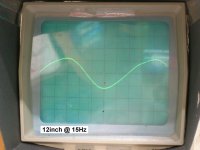
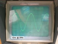
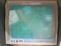
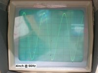
I tried to estimate the excursion by monitoring with an oscilloscope the EMF of the driven speaker.
At low frequencies, approx 1/2 Fs and below, the waveform produced by the EMF is distorted.
I checked it with three different speaker pairs, the oval (Fs 73Hz) , a 4inch mid woofer (Fs~100Hz) and a 12inch mid woofer (Fs~50Hz)
The compression – rarefaction of the air enclosed btn the two cones is not symmetric at these low frequencies.
George
(*) visual and haptic sensing of small differences works very well with two simultaneous stimuli, one working as a reference for the other)
Attachments
-
 12inch @ 15Hz.JPG321.8 KB · Views: 63
 -
 12inc @ 25Hz.JPG319.2 KB · Views: 65
 -
 4inch @ 43Hz.JPG306.1 KB · Views: 66
 -
 4inch @ 66Hz.JPG315.6 KB · Views: 188
 -
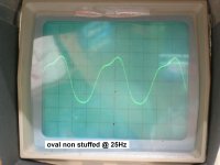 oval non stuffed @ 25Hz.JPG309 KB · Views: 182
 -
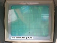 oval non stuffed @ 40Hz.JPG319 KB · Views: 187
 -
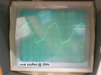 oval stuffed @ 25Hz.JPG322.1 KB · Views: 194
 -
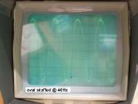 oval stuffed @ 40Hz.JPG332.2 KB · Views: 190
 -
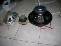 speaker pairs.JPG963.2 KB · Views: 67
Exciting like a novel ...The compression – rarefaction of the air enclosed btn the two cones is not symmetric at these low frequencies.
Why such a dissymmetry with such a small change of pression ? Asymmetric deformations of the speaker's suspensions ?
Last edited:
One would think we can design linear motion -at least the vc - for small excursions at least.
Why is this so hard to do? Other fields of engineering can make linear travel/displacement. Can't they?
Must be something fundamentally wrong here. Must be at the cones edge termination/suspension … maybe too short
We can make the mag field/vc linear motion but the cone tied to edge is bigger problem.
The Vc is potentially quite linear operation or capable of being so. But it is attached to edge suspension thru ridged cone. That edge pushes back on VC.
What if the edge suspension was wide and resembled the centering 'spider' suspension?
THx-RNMarsh
Last edited:
Any time the magnitude or phase of one cone is different from the other, the pressure and volume between the cones experiences changes. This modulates the compliance of the air cushion, generating distortion.
I don't know how much of a factor cone deflection is in the nonlinearity. However if both cones are moving in phase then the distortion would be minimized. Then you could simply decrease excursion to reduce the contribution from the suspension and cone deflection.
I don't know how much of a factor cone deflection is in the nonlinearity. However if both cones are moving in phase then the distortion would be minimized. Then you could simply decrease excursion to reduce the contribution from the suspension and cone deflection.
The compression and rarefaction of a gas enclosed in a variable volume is symmetric only if the state change is reversible, i.e. lossless.The compression – rarefaction of the air enclosed btn the two cones is not symmetric at these low frequencies.
If waves are generated, the compression and rarefaction ones always have different shapes, and their superposition can generate all sorts of waveforms.
I have a feeling that the system is too complex to be investigated in this manner. In accordance with the standard practice in modal analysis, the cone should be actuated mechanically, with a minimum of coupling between it and the exciter.
Regards,
Braca
One would think we can design linear motion -at least the vc - for small excursions at least.
Why is this so hard to do? Other fields of engineering can make linear travel/displacement. Can't they?
Must be something fundamentally wrong here. Must be at the cones edge termination/suspension … maybe too short
We can make the mag field/vc linear motion but the cone tied to edge is bigger problem.
The Vc is potentially quite linear operation or capable of being so. But it is attached to edge suspension thru ridged cone. That edge pushes back on VC.
What if the edge suspension was wide and resembled the centering 'spider' suspension?
THx-RNMarsh
You'd have to redesigns it to be minimal. As Keantoken is saying, you create and ugly floppy transducer.
You *might* get away with something like Oleg's spider. But I wouldn't be surprised to hear VC scratching.
You've got multiple problems. In order for a dynamic driver to be as linear as possible, it'll naturally gain as frequency increases. You put it an a horn for the inverse affect to balance it... Then you built a barn to house it in.

I think the whole VC to magnet thing is limited for possibilities. I don't have a good answer yet. I've thought about the possibility of having an electric motor that rotates under 1hz at rest, and then can rotate at given frequencies to drive a cone inside of a small cylinder like a piston... but then you need a way to change volume... centrify on a spring won't work. While this is no where nearer a working model than the stick transducer, what's important I think is that switching the drive type can eliminate the worry about weight, once you have sufficient driving force and counter force. No more needing the dainty suspension or cone materials.
Last edited:
Loudspeaker and Headphone Handbook - Google Books
The suspension is the greatest issue in non-linearity/distortion.
A large, wide centering suspension (accordian style also) is more linear than the short stiff cone edge suspension.
Magnetic centering/suspension may be best. Then only have the edge suspension to optimize.
THx-RNMarsh
The suspension is the greatest issue in non-linearity/distortion.
A large, wide centering suspension (accordian style also) is more linear than the short stiff cone edge suspension.
Magnetic centering/suspension may be best. Then only have the edge suspension to optimize.
THx-RNMarsh
Last edited:
You do not need my ok. I would gladly participate.I wasn't thinking so much of the technical aspect (although there's that) but right now all the nuggets are spread over dozens of pages in a mega thread that's gonna hit 30,000 again.
As well, AFAIK search engines have trouble digging things out of threads and do better with thread titles and post titles. Plus all the info would be condensed with no breakfast descriptions intervening.
So a dedicated thread with all the catch words in the title will be the most accessible for the next generation (those young punks google everything!
I wanted to get your ok, and some catch words for the title.
Cheers,
Jeff
Jn
The gap field is assymetrical front to back by design.One would think we can design linear motion -at least the vc - for small excursions at least.
Why is this so hard to do? Other fields of engineering can make linear travel/displacement. Can't they?
Must be something fundamentally wrong here. Must be at the cones edge termination/suspension … maybe too short
We can make the mag field/vc linear motion but the cone tied to edge is bigger problem.
The Vc is potentially quite linear operation or capable of being so. But it is attached to edge suspension thru ridged cone. That edge pushes back on VC.
What if the edge suspension was wide and resembled the centering 'spider' suspension?
THx-RNMarsh
The vc coupling to the magnetic structure is assymetrical by design.
The permeability of the iron at the gap surface is assymetrical by design.
The eddy losses in the iron gap surfaces caused by the vc audio currents are assymetrical by design.
It almost appears that there is some kind of trend here, although I can't seem to get a handle on what that might be...
Jn
- Status
- Not open for further replies.
- Home
- Member Areas
- The Lounge
- John Curl's Blowtorch preamplifier part III