Then why talk about it qusp? Talking 'around' a subject does little to inform.
I believe you are quite adept at that technique, John.
jn
ps. Did you really believe that, when handed a blank check, I would not cash it???
Then why talk about it qusp? Talking 'around' a subject does little to inform.
haha, because you said almost nothing about it, hell even your 'answer' was a bit vague and you think it was specific and informative? I answered with an inferred question mark, perhaps you are unable to see such things, but your post was not there when I formatted the reply. when starting a post with 'I believe' its usually, at least for me, an invitation for others to correct the content as required.
in fact, i'm not even sure what it is you are objecting to me talking about or saying, such is the depth of your arbitrariness; its what you live and breathe. it took you years to post anything worthy of specific technical discussion, preferring to dance around and dodge it as some kind of sport.
pot kettle John, pot kettle. i'm too full of irony to eat another bite
Last edited:
actually it seems I edited the inferred question mark into an actual one.
does the JC2 hold the patent for losing gain from the act of inverting the input? I dont think so, I thought it was normal for some of the gain to be used to invert the input. the +1 for the positive phase gain calc is missing for the negative phase. without using this circuit specifically G = (R2/R1) +1 but we dont have the '+1' for the - input, so some of the gain needs to be used to first copy and invert the signal before adding gain. is that clearer? or if wrong, how?
does the JC2 hold the patent for losing gain from the act of inverting the input? I dont think so, I thought it was normal for some of the gain to be used to invert the input. the +1 for the positive phase gain calc is missing for the negative phase. without using this circuit specifically G = (R2/R1) +1 but we dont have the '+1' for the - input, so some of the gain needs to be used to first copy and invert the signal before adding gain. is that clearer? or if wrong, how?
Last edited:
I really don't know, off-hand, quisp, any more than you do. I only know that it is a problem that had to be addressed.
That is why I had hoped that PMA, with his superior education and engineering skills, could explain it in engineering 'baby-talk' so that we could all understand it better.
That is why I had hoped that PMA, with his superior education and engineering skills, could explain it in engineering 'baby-talk' so that we could all understand it better.
i'm simply relating the same gain equation that would be used for a simple opamp circuit. treating the JC2 gain stage as an opamp for the purpose of simplification. I didnt think I had to explain where a simple derivation like G = (R2/R1) + 1 came from its so common...
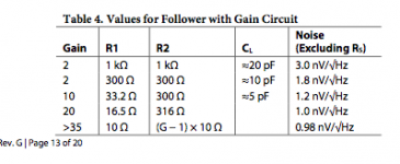
when you run an opamp as a follower with gain (non inverting) you get in simplest terms G = (R2/R1) +1 (the plus 1 is for the input, just the same as many adjustable IC regulators you will use the same calc taking the pre-existing internal +V reference into account) but if you use the same values for an inverting configuration you do not get this free +1 to start with, as you dont have a negative input signal term, the input is opposite in polarity to the desired output.
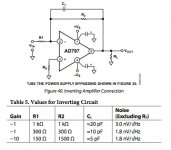
if you will, some excerpts from your favorite datasheet
notice the inverting gain always lacks the +1 in the suggested values, but the non-inverting gain does, as it has the positive input signal to add to the gain. so if we are lacking the +1 thats added to every calc, no-matter whether its (100Ω/10Ω) +1 = 11, or (4kΩ/200Ω) +1 = 21, as the gain increases, the contribution of the +1 is a smaller amount of the total, thus in inverse proportion to that increase, just as your example.
but the inverting results lack this +1, as it lacks an initial negative input voltage to add to the inverted gain, so it must use some gain of its own, meaning if the values are the same for each side of the circuit ie symmetrical and dont change for balanced vs SE converted, doesnt that make sense? if thats all sound, to equalize there would need to be attenuation on the non-inverting output that was increased in inverse proportion to the gain. ie as the gain was reduced, a larger proportion of the output would need to be attenuated.
i'm sure I could be missing something in your switching and conversion, its not easy to read and I have FAAAAAAAAAR from the experience of most other contributors in this thread and no education bar my self driven learning, the kind help of others and practice, practice practice.
ive gotta tell you, I just had another glance at the schematic of yours for a few minutes, its late and its hurting my head and eyes. Its drawn so convolutedly and seemingly with colours designed to induce an epileptic fit! i'm just about ready for bed and it isnt helping! is that deliberate, like a code? I gave up after a couple of minutes and im not near the bottom of it, i'll havce to print it out in B&W I think.
sorry for verbosity, I hope thats clear on the 3rd time, or at least if i'm confused, the source of my confusion is clearly pointed out.
when you run an opamp as a follower with gain (non inverting) you get in simplest terms G = (R2/R1) +1 (the plus 1 is for the input, just the same as many adjustable IC regulators you will use the same calc taking the pre-existing internal +V reference into account) but if you use the same values for an inverting configuration you do not get this free +1 to start with, as you dont have a negative input signal term, the input is opposite in polarity to the desired output.
if you will, some excerpts from your favorite datasheet
notice the inverting gain always lacks the +1 in the suggested values, but the non-inverting gain does, as it has the positive input signal to add to the gain. so if we are lacking the +1 thats added to every calc, no-matter whether its (100Ω/10Ω) +1 = 11, or (4kΩ/200Ω) +1 = 21, as the gain increases, the contribution of the +1 is a smaller amount of the total, thus in inverse proportion to that increase, just as your example.
but the inverting results lack this +1, as it lacks an initial negative input voltage to add to the inverted gain, so it must use some gain of its own, meaning if the values are the same for each side of the circuit ie symmetrical and dont change for balanced vs SE converted, doesnt that make sense? if thats all sound, to equalize there would need to be attenuation on the non-inverting output that was increased in inverse proportion to the gain. ie as the gain was reduced, a larger proportion of the output would need to be attenuated.
i'm sure I could be missing something in your switching and conversion, its not easy to read and I have FAAAAAAAAAR from the experience of most other contributors in this thread and no education bar my self driven learning, the kind help of others and practice, practice practice.
ive gotta tell you, I just had another glance at the schematic of yours for a few minutes, its late and its hurting my head and eyes. Its drawn so convolutedly and seemingly with colours designed to induce an epileptic fit! i'm just about ready for bed and it isnt helping! is that deliberate, like a code? I gave up after a couple of minutes and im not near the bottom of it, i'll havce to print it out in B&W I think.
sorry for verbosity, I hope thats clear on the 3rd time, or at least if i'm confused, the source of my confusion is clearly pointed out.
Attachments
Last edited:
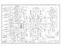
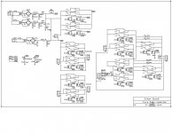
I didn't draw the schematic or even do the switching logic. I just oversaw that part. The schematic is made by 'Design Works' and it is one of the best schematic drawing programs available.
This schematic is rather complex due to the fact that the line stage has so many states: Balanced input, unbalanced input, balanced output and unbalanced outputs, also absolute polarity (remote controlled).
It is interesting that the Blowtorch circuit does NOT need so much added correction circuitry, because it doesn't have any global loop feedback.
I didn't say that we could have patented it, only that we had to 'fix' it. We did something similar with the JC-80.
I actually find the JC-80 schematic more interesting because it wraps the DC bias into the feedback network in a more complicated way.
hehe. i'd like to say much better, but its just better I do have the Adobe creative suite though is there a word for something that induces a form of visual epilepsy in those lacking the condition? I dunno, maybe its just narcolepsy ZZZZZzzzzzzzzzz catch you guys later.
the alternative is i've just been trolled as an instrument to get at PMA
I do have the Adobe creative suite though is there a word for something that induces a form of visual epilepsy in those lacking the condition? I dunno, maybe its just narcolepsy ZZZZZzzzzzzzzzz catch you guys later.the alternative is i've just been trolled as an instrument to get at PMA
that will require pain that i'm not quite ready for now. there are 4 input terminals for the SE input are there?
it was a conceptual simplification, you do realize that yes? the idea being that if its a symmetrical gain stage and apart from the attenuation network there is nothing switched into the gain network for the SE->BAL vs BAL->BAL the same effect can apply. if it doesnt, why? i'm going to bed, not attacking that schematic again now, as I said I was planning to look this weekend.
you tell me? you tell me why it needs attenuating in that specific way?
Last edited:
i'm sure I could be missing something in your switching and conversion, its not easy to read and I have FAAAAAAAAAR from the experience of most other contributors in this thread and no education bar my self driven learning, the kind help of others and practice, practice practice.
ive gotta tell you, I just had another glance at the schematic of yours for a few minutes, its late and its hurting my head and eyes. Its drawn so convolutedly and seemingly with colours designed to induce an epileptic fit! i'm just about ready for bed and it isnt helping! is that deliberate, like a code? I gave up after a couple of minutes and im not near the bottom of it, i'll havce to print it out in B&W I think.
I have worked with a variation on that design for months now. At first its really daunting to understand. Break it into component segments and ignore the switching or you will never get it. Its almost a mandala, working from the center out. A form of almost radial symmetry. It also helps to divide the gain stage in two down the middle. In practice, except for the feedback, the two haves don't interact much.
The servos are also interesting in that they are a common mode and a differential mode servo.
The input switching is messy, but it always is when balanced and unbalanced systems attempt to share. I would work back from the gain terminals, not from the I/O connections.
And when you're done, you can read a treatment of the same question by someone who bases his opinions on actual engineering and evidence rather than fashion.
http://www.linearaudio.net/images/onlinearticlesPDF/volume1bp.pdf
SY, thank you. You are so kind - thank you again. If you will tell me news, yes I knew that what's written in the article.
My post was not a question, please read between the lines. My opinion comes from my experiences. No fashion, only my experience in music reproduction and listening.
Thank you again for your kind teachings.
A personal gripe apropos the diagram: (not directed at JC)
It is very difficult to understand with so many wires flying all over the place!
I always found it best to separate the relay coils and logic onto a separate sheet and then use a meaningful label for the relay contact,
e.g "K3-unbalanced."
This brings up a wider point - what (who!) is the schematic FOR?
Obviously it is needed initially as input to the PCB layout and BOM, but generally not for manufacture. Years later, for those installing, debugging and repairing it is often the only source of information. Schematics should be annotated accordingly.
Tek 'scope manuals were my inspiration.
You poor guys, I give you a REAL schematic and you want a Tek manual. '-)
The point of me putting this schematic up is: To show what 20 years of evolution did for the JC-80, using alternative parts, how a REAL PREAMP with a number of features, is made, and one that hopefully has as few 'compromises' as possible.
This design was made by the same CTC team that made the Blowtorch, but for a different factory, and market. It is the HONDA compared to the PORSCHE.
This is the only schematic that my associates and I ever made. I am sure that the Taiwanese have their own modified schematics, but I have never seen them.
I knew that this schematic is rather complex, AND that the switching was NOT really part of of the initial discussion, but it was on the original schematic so it got shown. Just ignore the switching, and compare what is left with the JC-80 schematic of 30 years ago. You will find that they are very similar in topology, just a different approach, because of what was available at the time of fabrication, and the need for a 'less fussy' product.
If I was to remark on the 'fussiness' in the construction parameters of some of my preamps: I would rank the CTC Blowtorch as 1, the JC-80 as 2, and the Parasound JC-2 as 3, etc. I can't give total strangers more responsibility for matching, etc than they want or need.
- Status
- Not open for further replies.
- Home
- Member Areas
- The Lounge
- John Curl's Blowtorch preamplifier part II