

flg, another approach is to use an isolated split secondary and to then rectify and regulate each of these secondaries and then to connect the ground of the one supply to the + of the other supply to create a split supply.
The advantage to this is you can stick with LM317's -they are much better than the 337's, and all the associated components are of the same polarity. Its also easier to manage the layout and grounding around the rectifiers and filter caps.
AMVECO do some nice split secondary transformers, but if you can ge t R-core, that's better still.
John,
On the subject of unobtainium output devices:
Have you ever looked at the lateral mosfets that are sold by Profusion in the UK?
http://www.profusionplc.com/pro/gex/prodGen.html?prdtyp=lateral mosfet
I have used some of their units to restore older amps where the original mosfets are no longer available. Profusion also supply some of the smaller 'hi-end' outfits that still swear by lateral mosfets like some here")
Worth a look-see.
Jan Didden
On the subject of unobtainium output devices:
Have you ever looked at the lateral mosfets that are sold by Profusion in the UK?
http://www.profusionplc.com/pro/gex/prodGen.html?prdtyp=lateral mosfet
I have used some of their units to restore older amps where the original mosfets are no longer available. Profusion also supply some of the smaller 'hi-end' outfits that still swear by lateral mosfets like some here
Worth a look-see.
Jan Didden
Bonsai said:flg, another approach is to use an isolated split secondary and to then rectify and regulate each of these secondaries and then to connect the ground of the one supply to the + of the other supply to create a split supply.
The advantage to this is you can stick with LM317's -they are much better than the 337's, and all the associated components are of the same polarity. Its also easier to manage the layout and grounding around the rectifiers and filter caps.
AMVECO do some nice split secondary transformers, but if you can ge t R-core, that's better still.
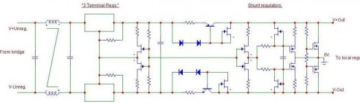
Use a single floating supply, current source (throw away a volt or two on resistors) and stacked shunts. No path to ground except the one that you define. If you keep the currents balanced between supplies there will be no circulating currents in the grounds. It can also be short circuit proof with a little effort.
HI All
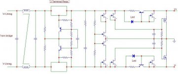
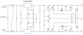
Thank you flg for showing us these old schematics, I lost them when my server “crashed”.
Since then, gradually, I came to these configurations:
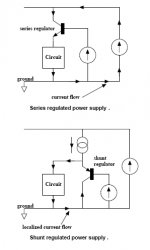
Series PSU
Shunt PSU
Thank you flg for showing us these old schematics, I lost them when my server “crashed”.
Since then, gradually, I came to these configurations:
Series PSU
Shunt PSU
"Use a single floating supply, current source (throw away a volt or two on resistors) and stacked shunts. No path to ground except the one that you define. If you keep the currents balanced between supplies there will be no circulating currents in the grounds. It can also be short circuit proof with a little effort.
"
agree - this is also an alternative approach.
"
agree - this is also an alternative approach.
Jung super regulators are often called Jung /Didden regulators since you are co-author and PCB designer. They have almost perfect measured specifications, lowest noise and output impendance. Inserting open-loop shunt between Jung series regulator and audio stage, as you suggest, will degrade measured performance.janneman said:
No, after! The great advantage of a shunt is that it lets you localize the return current, rather than running it back through the ground wire to the supply input, with the risk that it contaminates the signal ground.
Jan Didden
kamis said:
Jung super regulators are often called Jung /Didden regulators since you are co-author and PCB designer. They have almost perfect measured specifications, lowest noise and output impendance. Inserting open-loop shunt between Jung series regulator and audio stage, as you suggest, will degrade measured performance.
Well, I would never use an open loop shunt (I'm not sure I know what that is even, is that just a fixed DC current source?). But a shunt can be very usefull if placed near the load because it allows you to keep all ground currents local.
Even with a perfect series regulator, the ground current varies with the signal and has to go back to the supply caps. If more than one stage shares ground wires that can increase noise and distortion.
The ground current with a shunt back to the supply cap is constant (DC) because the sum of load current and shunt current is constant (= the CCS current). So mutual influence between stages is much less. But it anyway depends a lot on the implementation, you really have to know what you are doing of course.
Jan Didden
Attachments
john curl said:Anybody find any complementary mosfet 1A devices in a TO-220 package around that have good matched output Z?
Doesn't exist and it can't be done while keeping all other parameters (transconductance, etc...) matched. The MOSFET output conductance is Go~Lambda*Id where Lambda in the channel legth modulation coefficient which, because of the different properties of the P and N doped silicon, is significantlyy different between N and P devices.
You best bet is to use low voltage devices with as high as possible transconductance. Such devices have very small Lambdas and therefore very large output impedance.
janneman said:If capacitances aren't much of an issue, you could use 1 N and 2 parallel P channel devices, I remember in the past using this because the P channel had about half the transconductance of one N.
This is the main issue in matching MOSFET devices. You either match for capacitances (and then you get the IRF pairs) or you match for transconductance (and then you get the Toshiba 2SK1530/2SJ201 pairs). Unfortunately, the ratio is never exactly 2, but more like 1.7 ... 1.8
I'm looking forward for quite some time to figure out how to optimally use the cheap IRF or equivalent devices in complementary power stages, but never had the time for. Perhaps later this year...
EDIT: Strictly from a datasheet perspective, an IRF MOSFET matching part is not IRFP240/IRFP9240 but IRFP244/IRFP9240. This should be theoretically at around the same performance level as the Toshiba pairs, of course this has to be experimented and confirmed. These IRF pairs are about three times less expensive than Toshiba!
Perhaps someone could explain the function of the the series pass transistor and fet combination that seems to sit on the rails in post http://www.diyaudio.com/forums/showthread.php?postid=1870157#post1870157 ??
I suspect that many readers are unsure how this bit functions without an external reference, or what it is intended to do...
_-_-bear
I suspect that many readers are unsure how this bit functions without an external reference, or what it is intended to do...
_-_-bear
- Status
- Not open for further replies.
- Home
- Member Areas
- The Lounge
- John Curl's Blowtorch preamplifier part II