We have no real info about the new ADA input stage circuit connection, and I doubt Scott is going to disclose it here. So no 'analysis' can be done.
Maybe US patent 6087883 Analog Devices ?
Multi-tanh cells constructed in accordance with the present invention provide improved input voltage range by utilizing resistors connected between the emitters of the transistors and the corresponding bias current sources. The resistor values and emitter area ratios are chosen to achieve...
http://www.google.com/patents/about?id=uAgEAAAAEBAJ&dq=6087883
some questions
hi..i have several questions
1)can i use matched bc557c bc556c instead of 2n4401/4402?should i make some changes on the circuit..a
2) can i use this circuit to drive my sennheiser hd25 dj headphones?is the power of preamp enough to drive them?
3)can i use it as an unbalanced preamp?because it seems a balanced preamp. thanks
Attachments
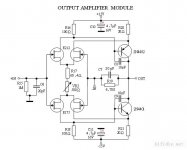
First, umut101. This schematic, as presented has a serious error in that the first stage output leads are switched. The circuit will not work as it is presented in this schematic. This is a 36 year old design, and was published 32 years ago, and the parts are all obsolete. Originally, we used TO-5, 2W devices with heat sinks for outputs, then went to TO-92 for the Levinson JC-2 output stage with thermal epoxy for improving the TO-92 thermal performance, and making it acceptable. In any case, it will NOT drive a headphone properly, because it is a transconductance amp, and is highly dependent on the load impedance. Even in the original design, the minimum load was 600 ohms. With the TO-92 devices, perhaps 2K ohms.
Therefore, it is best not to use this approach for a headphone amp.
Therefore, it is best not to use this approach for a headphone amp.
Second, the answer is now clear enough, at least for me.
First, I had to ascertain who designed the circuit, since the schematic is not available on the spec sheet, hoping to reason out, or ask the designer, which multi-tanh approach was used for the input stage. With the help of Scott Wurcer, and others, (thanks everyone, whoever you are) we found that the design of the ADA4898 was done by Nathan, on the West Coast of the USA. Nathan has a patent for his very own multi-tanh input stage, and it has the patent number: 6,963,244 (supplied here by several engineers, thanks again)
Looking at fig. 4 on the patent for different values of A, shows that 4 is the closest prospect. It is very flat, and not as worrisome to me, as I had been concerned about some of Barrie Gilbert's examples. I would certainly take a chance on this design. It is being independently evaluated by someone here, and I await the results. However, Scott did warn me of the 'lean' output stage, and we might have to do something about that. Yes, golden ears can actually hear the difference, even if the distortion is very low. I will leave that to the research of others, as to why.
Last edited:
Well everyone, was I clear enough on my last post of multi-tanh?
I got the answer that I needed (mostly) by just asking my colleagues enough questions and getting answers.
This is a form of engineering, akin to Tom Sawyer getting his friends to 'whitewash' the fence with him.
Please, I wish not to speak historically or without purpose, but it just so happens that 25 years ago, a colleague of mine, named Scott Wurcer, (our very same), helped me out in a big way, on RF cap bypassing.
You see, the company that I worked for at the time, directed me to build an RF power amp that operated about 30MHz and had to be switched on and off very quickly.
I telephoned Scott, and he told me which type of ceramic caps to use, and he sent me a sheath of papers by mail, that were the results of his previous study on cap bypassing, AND with specific measurements and recommendations. It saved me a lot of time and trouble, so thanks again, Scott.
However, I got into trouble with my boss, the VP, because my office partner, a fellow Sr electronic engineer (we had the same title) complained that I was on the phone a lot, and that I discussed audio, sometimes.
He heard selectively, because most of the time I was getting answers from people with more experience than me, but then I was often asked by them, to return the favor by answering their audio questions. Can you imagine how much time you can save by asking the right people, the right questions, before you just blindly go ahead with the project?
Last edited:
Ever onward (continued), getting back to the design of power supplies, as we were at 30 years ago. Now, what has happened since?
We have looked further at the problems that typical IC regulators present, in general. First, they are noisy. Second, they tend to overshoot on transients. Third, they collapse almost completely at very high frequencies like 1 MHz or so, and will not isolate digital signals at those frequencies and above. And finally, they don't like to be terminated by super high Q caps, electrolytic, or otherwise, because that makes their noise peak inside the audio band.
Have I missed anything, anyone?
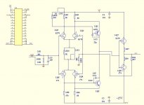
Hi umut1001,
you might want to look at this thread:
http://www.diyaudio.com/forums/solid-state/10160-need-build-jc-2-preamp.html
it deals with the circuit you are referring too.
you might want to look at this thread:
http://www.diyaudio.com/forums/solid-state/10160-need-build-jc-2-preamp.html
it deals with the circuit you are referring too.
regulators
Yes. Reading the application notes of these parts.
..............
Have I missed anything, anyone?
Yes. Reading the application notes of these parts.
Guys, John appears to be making an effort to change his communication manners lately.
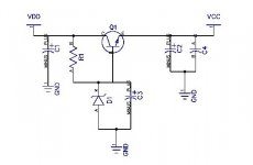
I think analyzing Joshua's regulator is a very good and productive exercise for this thread, so I anxiously wait for John's comments. There's always something new to learn in this thread.
Joshua G, your example has only one major problem. You should put a resistor of 1K ohm or so between the Zener diode and the cap which should be connected to the base of the transistor. This will lower the noise generated by the Zener diode, significantly. In fact, this is one of the major tradeoffs of using the 3 terminal IC regulators, that is: no way to bypass the solid state reference.
- Status
- Not open for further replies.
- Home
- Member Areas
- The Lounge
- John Curl's Blowtorch preamplifier part II