How could you have overlooked the actual key point that Malcolm stated:
"Modulating the OL transfer function
means you modulate the circuit’s
closed-loop (CL) phase shift. What is
interesting is that it looks remarkably
similar to correlated jitter; they share
a family resemblance (Fig. 3). It also is
similar to what people have been talking
about as dynamic-phase modulation in
amplifiers."
How would one actually construct a test for this test this thesis? Essentially the claim is that a voltage modulation will cause a timing shift. Differential phase/differential gain measurement? Unfortunately 3.58 MHz is beyond the passband for most audio products so we can't use the discarded NTSC measurement stuff so how would we measure this and put the arm waving to test?
What type (ie, brand, model, and value) have you tried in this position, and what DAC chips did you try this with?
I've tried with BB/TI and ADI dacs, admittedly not in that exact configuration and not always with the same opamps.
Let me take one, more specific, example, with TDA1543 running at 44k1 using passive I/V - I first listened with some polyprop - the Wima green box types. I also tried some (presumably TDK or perhaps AVX) NP0 ceramics with the same effect. Note this case doesn't include any opamp. With the TI/BB (PCM1792) and ADI (AD1955) cases, there was an opamp and the cap was actually around the opamp (that is -ve input to out) rather than direct to ground. I think (but I'm not sure, my memory's a bit hazy) I tried a cap direct to ground with the AD1955 but got horrible ringing so I took it out.
In all those cases the value of 2n2 (or thereabouts) sounded worse than lower values (or none at all in the case of the TDA1543). At least two guys on Head-fi have found a similar effect with this same DAC using passive I/V.
<edit> Which DACs and opamps have you tried it with?
Last edited:
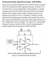
comparisons are becoming more complicated with ladder DACs, NOS being a decidedly "fringe" situation even for audiophiles - Sigma-Delta "thermometer code" or multibit segmented DWA techniques are pretty much the mode for the last few generations of "flagship" audio DAC
but the adequately linear, somewhat recent ladder DACs support reasonable 8x -16x oversampling - which directly reduces step size for CD band limited music by the ~OS factor
the amplitude and area of the switching transient Verror at the op amp input driving the diff pair into nonlinear operation is the fundamental mechanism Malcom models as the error source for feedback I/V
smaller steps, working into the tanh, ~3rd order BJT diff pair nonnlinearity give ~ 8^2 = 64x less distortion with 8x OS
we can also use ~10x faster op amps today than a unity compensated 5532
fet input op amps with their more linear inputs are available too at these faster speeds - but the audio noise performance isn't so good
and I can't understand Analog Devices "hiding" the new input linearization - not crowing about it, linking the patent, showing the input gm linearization for the AD8099, ada4898 families - could be today's best DAC I/V single op amps as I read the specs
Hawksford even proposed much higher feedback multiloop DAC I/V in his paper (my op amp choices in the sim - Malcolm used TL074)
http://www.essex.ac.uk/csee/researc...Current steering transimpedance amplifier.pdf
Attachments
Last edited:
I've tried with BB/TI and ADI dacs, admittedly not in that exact configuration and not always with the same opamps.
Let me take one, more specific, example, with TDA1543 running at 44k1 using passive I/V - I first listened with some polyprop - the Wima green box types. I also tried some (presumably TDK or perhaps AVX) NP0 ceramics with the same effect. Note this case doesn't include any opamp. With the TI/BB (PCM1792) and ADI (AD1955) cases, there was an opamp and the cap was actually around the opamp (that is -ve input to out) rather than direct to ground. I think (but I'm not sure, my memory's a bit hazy) I tried a cap direct to ground with the AD1955 but got horrible ringing so I took it out.
In all those cases the value of 2n2 (or thereabouts) sounded worse than lower values (or none at all in the case of the TDA1543). At least two guys on Head-fi have found a similar effect with this same DAC using passive I/V.
<edit> Which DACs and opamps have you tried it with?
The last time I used an op-amp in or near the signal path was in the power supply regulator of a modified Dyna Stereo 70 tube amp, over twenty years ago.
 It was god-awful sounding. Took it out and could once again listen to the amp for more than five minutes without getting a headache.
You have made some errors in at least some of your test setups. You say with the PCM1792 and the AD1955 that the cap was NOT to ground, but instead in the feedback loop of the op-amp. Which means that you missed the point of Scott's post completely. Maybe he will repeat his shenanigans from that AES session and make a post saying that we should all just listen to SET amps...
The last time I used an op-amp in or near the signal path was in the power supply regulator of a modified Dyna Stereo 70 tube amp, over twenty years ago.
Not my experience at all - opamps sound fine given the right circuit conditions - which isn't usually the output of a DAC I must admit. Perhaps your regulator had other serious flaws.
You have made some errors in at least some of your test setups.
I might have made an error in over-generalising my conclusion from some disparate setups, sure. But then so must have you because you haven't listened to opamps on the output of DACs by your own admission. I'm not claiming that my setups were identical to Scott's - far from it since I've never played with the AD797.
You say with the PCM1792 and the AD1955 that the cap was NOT to ground, but instead in the feedback loop of the op-amp.
As I mentioned I think I tried it to ground and didn't like the look of the resulting waveform one bit. With the PCM1792 you're correct, I only tried it around the opamp and not to ground. Are you saying that this different case from Scott's (which I don't dispute) invalidates listening results from the TDA1543 case? If it does then your listening cases are equally invalidated being as they were without opamps. My TDA1543 case had subsequent opamps (in active filters) but not as I/V.
Which means that you missed the point of Scott's post completely.
How so? His point was that the cap protects the opamp from nasty edges by filtering them to ground. My point was that in doing so (which I don't dispute) it tends to mangle the sound. Having an opamp post the relative mangling which is going on doesn't recover the original sound quality (so it seems to me).
So - given that you don't like to use opamps, the DAC part of my earlier question still stands. Which DACs have you put caps on the output of and liked the resulting sound better than without? You can't have listened with Scott's configuration either, owing to your aversion to opamps, so what setup did you listen to?
Charles,
I am sorry to learn you can't design a power supply regulator! (At least according to some here...) After all the insight you have shown on the design and critical issues in audio reproduction would have left me with the impression you might know what you are talking about. Oh well, I guess I will have to turn elsewhere for insights.
One of the issues I have is that when I write article is that I try to stick to tutorials and show reasonably good methods but without disclosing anything that I learned confidentially about circuit design. That is why I am so impressed with some of what you are willing to openly discuss.
Demian,
The method to test for differential phase in audio amplifiers is an interesting one. Kind of on my mind for a while know. Also I really do not like the term PIM as most folks who use it mean Passive Intermodulation Distortion a very big issue if you are building cell phone tower equipment!
ES
I am sorry to learn you can't design a power supply regulator!
(At least according to some here...) After all the insight you have shown on the design and critical issues in audio reproduction would have left me with the impression you might know what you are talking about. Oh well, I guess I will have to turn elsewhere for insights.One of the issues I have is that when I write article is that I try to stick to tutorials and show reasonably good methods but without disclosing anything that I learned confidentially about circuit design. That is why I am so impressed with some of what you are willing to openly discuss.
Demian,
The method to test for differential phase in audio amplifiers is an interesting one. Kind of on my mind for a while know. Also I really do not like the term PIM as most folks who use it mean Passive Intermodulation Distortion a very big issue if you are building cell phone tower equipment!
ES
@Simon7000
PIM is used in two different meanings, in this thread I hold it to be the accronym for phase intermodulation distortion, since we are discussing audio and not HF.
If it happens, it would be a bad thing for imaging amongst others. But according to http://www.cordellaudio.com/papers/phase_intermodulation_distortion.pdf
it is not a real problem in audio amplifiers, and can be improved by applying feedback. In the paper a method to test for PIM is explained.
vac
Last edited:
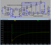
Here's one option, maybe a bit long in the tooth...
Scott,
I might be in need of a little education here.
Looking at the schematic, I would say C1 shunts high frequency input to ground. Cf is a shelving high pass in the feedback loop, so that would translate into a shelving low pass for the unit.
However, the text says that Cf shunts high frequency to ground. To me, Cf would seem to filter out some high frequency; not by tying it to ground, but because of its place in the feedback loop. Me no comprendo.
vac
Last edited:
PIM is used in two different meanings, in this thread I hold it to be the accronym for phase intermodulation distortion, since we are discussing audio and not HF.
If it happens, it would be a bad thing for imaging amongst others. But according to http://www.cordellaudio.com/papers/phase_intermodulation_distortion.pdf
it is not a real problem in audio amplifiers, and can be improved by applying feedback. In the paper a method to test for PIM is explained.
vac
Try Google for PIM distortion. Jargon is just a method to confuse the uninitiated.
Bob Cordell does a very nice job particularly in his book of presenting a lot of good basic information. Sometimes verifying or going beyond it is useful.
However, the text says that Cf shunts high frequency to ground. To me, Cf would seem to filter out some high frequency; not by tying it to ground, but because of its place in the feedback loop.
Perhaps you could say it shunts to virtual ground.
Me, I like the approach. My I/V consists of a fat Fet used Common-Gate, and
the capacitance of the device just eats up those high frequencies without
burping.
 OT posts removed
That is why I am so impressed with some of what you are willing to openly discuss.
Thanks for the kind words. On the one hand, you are probably right -- there is no reason to go around giving away secrets to potential competitors. On the other hand, there is no way to keep the details of anything secret, just as there is no way to make a bicycle lock that will never fail.
I have seen this phenomenon occur fairly often. Let's say that someone comes up with a novel and superior way to address a problem. Patenting it useless. Even Harman, who reached $6 billion at their peak wouldn't try to defend some of their weaker patents. So you can try to keep it secret. But it's really hard to sell something if you can't tell them how it works or why it is better. Look where that approach got Tice -- once the dominant player in power line filters, they are long out of business because of their "Magic Clock", which they steadfastly refused to divulge the details thereof.
I think it actually helps you when somebody copies you. That way instead of being the only "crazy" out there doing something, you were the company that blazed the trail that many follow. Here are some examples:
1) When we started Ayre, the only company of note that built equipment with balanced connections was Jeff Rowland. We pushed that concept very hard, and one-by-one, more and more companies followed suit. Now it is hard to find a top-level solid-state design that doesn't offer balanced. (There are even quite a few balanced tube products out there also.)
2) It's been slower, but even balanced phono stages are catching on. Again, Rowland beat us to the mark by several years, but we have had a balanced input-circuit-output phono stage continuously available for fifteen years. There was quite a stretch when Rowland stopped making phono stages altogether.
3) The only zero-feedback solid-state designs (that I am aware of) that preceded ours were those of Wingate Audio. (See post http://www.diyaudio.com/forums/solid-state/29464-another-zero-feedback-amplifier.html) They were out of business several years before I started my company and I knew little about the design. I didn't know that he had a patent on his circuit or I would have sent the $2 in that a copy of a US patent used to cost. Now with the internet, it is free. I wanted to track Steve Wingate down and interview him to develop an informal history of zero-feedback solid-state designs, but he unfortunately died just this past year.
At any rate, I wouldn't say that true zero-feedback amplifiers are common, but they are not the rarity now that they once were. In fact it amuses me to see the great lengths that other company's marketing departments will go to in order to seem as if they are using zero-feedback circuits.
One competitor proudly shows on their web site how one can connect two op-amps in series, each with a feedback loop around it and a third feedback loop around the whole shebang. Then they show how you remove that third feedback loop to achieve "zero global feedback"! I can't decide if it is laughable or just pathetic. It certainly is designed to deceive the customer.
Another competitor released an ultra expensive pre/power combo a few years ago. They boasted how the preamp was a "zero feedback" design, but they admitted that the power amp still used 8 dB of feedback -- which left me wondering what problem it was that they couldn't solve.
You see, I tend to be a black-and-white kind of guy. If feedback is good, then use as much of it as possible. If feedback is bad, then don't use any of it. I don't subscribe to the "I listened for three months and found the perfect amount of feedback to use" approach. Having said that, there are a few phenomenon that inextricably affect two separate parameters at the same time. Often as one gets worse, the other gets better. Then one does have to find the "sweet spot" where the two lines cross. But this kind of thing is very rare. A better approach in those types of situations is to extricate the two parameters and optimize them both individually.
There is also the area of practical considerations. Class A tends to sound better than class AB in power amps. But once you get past 25 or maybe 50 watts, you have something that is completely impractical. And there aren't that many people that want to spend tens of thousands of dollars for a 25 watt amplifier. Which also brings up the area of cost. Our top models are expensive, but not stupidly so. We keep getting requests from our dealers and distributors to make stupidly expensive gear as they can actually sell it. Go figure...
Enough rambling. I'll let somebody else have the floor now.
Here's one option, maybe a bit long in the tooth...
They didn't get it the first time, I don't think they are going to get it the second time either. I wish I had been at that AES Conference!
Scott,
I might be in need of a little education here.
Looking at the schematic, I would say C1 shunts high frequency input to ground. Cf is a shelving high pass in the feedback loop, so that would translate into a shelving low pass for the unit.
However, the text says that Cf shunts high frequency to ground. To me, Cf would seem to filter out some high frequency; not by tying it to ground, but because of its place in the feedback loop. Me no comprendo.
vac
It's called a "typo". Happens to even the best companies.
So putting a cap as a low-pass filter at the output of a current-output DAC chip "mangles the sound", but putting the same cap elsewhere in the circuit as a low-pass filter doesn't "mangle the sound"?
Any ideas why that would be?
Yeah I do have one. I'll offer it if and when you engage in dialog by responding to my question.
On the one hand, you are probably right -- there is no reason to go around giving away secrets to potential competitors. On the other hand, there is no way to keep the details of anything secret, just as there is no way to make a bicycle lock that will never fail.
You probably have heard this from me before:
My experience is that your real competitors will not copy your designs - they
have their own hobby horse and usually are too busy bad-mouthing your
design anyway.
Theft that does occur is most often simply stealing your trademarks.
You probably have heard this from me before:
My experience is that your real competitors will not copy your designs - they
have their own hobby horse and usually are too busy bad-mouthing your
design anyway.
Theft that does occur is most often simply stealing your trademarks.
That is, untill you invent something that is obviously better by an appreciable margin. Big industry will steal in such a situation, so you better be covering your a** with IP protection as much as you can afford.
However, and this is where I think the system is going to ****. Lawyers are bloody expensive, and just the USPTO filing fees for a PCT patent application are already >5K$. Going international with that same application, could easily cost you more than what you communicated to be your recent investment in carbon silicon JFET's. That is a big gamble. So you really have to be convinced that what you can claim is significally better, and also that there is a market out there that is willing to pay an extra margin for it.
If one doesn't think he can recoup his IP investments, the only alternative is to throw out your inventions into the public domain, so that at least no one else can put claims on it. Otherwise, you might find yourself in the situation where you are precluded from using your own innovations. (That is the reason why the inventor of the heading lock gyro, Colin Mills, published his invention rather than patent it. He could have been filthily rich and unhappy by now.)
So, what you are doing with publishing your designs also makes sense from an IP point of view. Unfortunately. From where I stand, the IP protection system has run completely off track cost wise, and the non-big money innovators with the big ideas suffer from it.
vac
Last edited:
But it's really hard to sell something if you can't tell them how it works or why it is better.
You mean people don't buy things for how they sound?
se
- Status
- Not open for further replies.
- Home
- Member Areas
- The Lounge
- John Curl's Blowtorch preamplifier part II