Hi,
Let us think up a really bad Amp, shall we? I know I am building "strawmen", then again, seeing many a project here one may be disincined towards the "strawmen" theory.
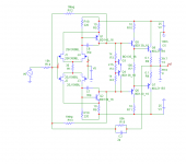
The IPS is bipolar, undegenrated, current mirror loaded and as we have neither read Self or Cordell we use an unbuffered and undegenerated VAS, single ended.
Now I recently did the workup of one of these for a particular project of mine and without Simulator. In my case I estimated the early effect collector impedance to vary from 5K (at one rail) via 12K (midpoint) to 20K (the other rail) from the datasheet. The transistor I had in my circuit is one actually legendary for it's linearity.
Now let us combine this VAS with a Vertical Fet output stage (let us use several in parallel, old faithful IRF240/9240 without drivers), where the capacitance can vary in the vicinity of 3:1 between midpoint and rail.
With so much load capacitance we don't even need miller compensation (if we are building a strawman we may as well do a good job).
Now this amplifier will have an open loop bandwidth that is signal modulated between around 600Hz and 3.2KHz and the open loop DC gain is around 86dB, but also varies with signal between around 78dB and 90dB.
The amount of front-end distortion I do not even want to estimate roughly, but it is going to be easily several percent open loop.
Lets close that loop as a global loop, shall we, for 26dB gain?
Now at "midpoint" all is well, we have 3.2MHz closed loop bandwidth and our several percent of THD from the frontend become 0.00several percent, in theory.
Yet the bandwidth varies between 1MHz at the rails and 3.2MHz at midpoint.
Of course, we can add degeneration and local feedback loops to reduce the bandwidth and gain modulation while also reducing the open loop gain and the front end distortion. But according to some the resulting amplifier will behave no different than if we use only the global loop. Or will it?
Ciao T
The question I have not been able to answer from this whole discussion above on feedback is the impact this might have on phase intermodulation.
Let us think up a really bad Amp, shall we? I know I am building "strawmen", then again, seeing many a project here one may be disincined towards the "strawmen" theory.
The IPS is bipolar, undegenrated, current mirror loaded and as we have neither read Self or Cordell we use an unbuffered and undegenerated VAS, single ended.
Now I recently did the workup of one of these for a particular project of mine and without Simulator. In my case I estimated the early effect collector impedance to vary from 5K (at one rail) via 12K (midpoint) to 20K (the other rail) from the datasheet. The transistor I had in my circuit is one actually legendary for it's linearity.
Now let us combine this VAS with a Vertical Fet output stage (let us use several in parallel, old faithful IRF240/9240 without drivers), where the capacitance can vary in the vicinity of 3:1 between midpoint and rail.
With so much load capacitance we don't even need miller compensation (if we are building a strawman we may as well do a good job).
Now this amplifier will have an open loop bandwidth that is signal modulated between around 600Hz and 3.2KHz and the open loop DC gain is around 86dB, but also varies with signal between around 78dB and 90dB.
The amount of front-end distortion I do not even want to estimate roughly, but it is going to be easily several percent open loop.
Lets close that loop as a global loop, shall we, for 26dB gain?
Now at "midpoint" all is well, we have 3.2MHz closed loop bandwidth and our several percent of THD from the frontend become 0.00several percent, in theory.
Yet the bandwidth varies between 1MHz at the rails and 3.2MHz at midpoint.
Of course, we can add degeneration and local feedback loops to reduce the bandwidth and gain modulation while also reducing the open loop gain and the front end distortion. But according to some the resulting amplifier will behave no different than if we use only the global loop. Or will it?
Ciao T
Ed,
I know what you mean, but certainly you are aware of the fact that I not only simulate the amplifiers, but also design and build them. I cannot imagine the situation how to get -80dB at 9th with even average design. -80dB at 9th may result from:
- very poorly designed underbiased output stage, i.e. crossover distortion
- very strange circuit design (yes I know examples of such amplifiers)
Regards,
Pavel,
I am aware that you are gaining on being a recognized designer of high end audio products.
But I do have salesmen show up with products that do not meet -80 on the 9th harmonic at typical output levels. So while around here most would get a chuckle out of such bad performance, there really are folks selling products that are that bad. (Usually at a very low price, but every so often at a very high price.)
ES
Hi,
Of course, we can add degeneration and local feedback loops to reduce the bandwidth and gain modulation while also reducing the open loop gain and the front end distortion. But according to some the resulting amplifier will behave no different than if we use only the global loop. Or will it?
Ciao T
Never said degeneration was the same it is different. Without changing the front end gm or linearizing it (multi-tanh JFET vs bipolar degeneration, etc.) I would like to see an example of reducing front end distortion.
Your example has nothing to do with the nail everyone has been hanging PIM on, Barrie talks about the gm modulation with current at the input and C.
BTW before you accuse me of not looking at things, do you really mean that you can't see by inspection (little block diagram in your head) that current or voltage demand at the input of the OS causes a larger error at the output with the 500k resistor?
Off to order new glasses, I've been making too many typos.
Last edited:
Scott,
I agree, in polite conversation you calrify and debate.
However as you insist providing "proof" of your position by simulating thing other than being discussed and prefer to jump with both feet on any post that advances a position you disagree with, without asking clarification etc. I figured we where past polite debate of ideas and into the "attack an idea" phase.
The circuit you simmed was not the JC-3 circuit published. The devices used where not the devices in the original publication. The Circuit you explicitly simmed omitted an output stage at first and after adding it because I criticised this you added an unloaded EF1 follower instead of an EF2 with a certain bias and load.
In other words, you completely went out of your way to avoind to get even within the same ballpark as the circuit you claimed to simulating. On top of that, in face of the simple criticism that your experiment does not even remotely match the original publication you contribute much verbiage, but no correction.
As it so happens my copy of PSpice stopped working after I upgraded to Win 7 so right now I live in a simulation free zone and cannot illustrate the real situation directly.
So, if you are right anyway, why not show a full JC-3 sim, using the devices proscribed and then omit the local loop? Show FFT for HD at 1, 10 and 100KHz and also add signals for TIM/SID diagnosis and show the result again. Your Sim SW seems much better than mine anyway.
If your position is true then all these sims will give identical results and we will have learned something. If not we have all learned something as well. From where I stand we all, you included, can only gain from the truth, why fight it so hard?
Ciao T
Sorry I was trying to make a list and was typing too fast, I meant to be inclusive to most if not all input circuits that output a differential current in response to a differential voltage. You love the opportunity to jump on any mis-speak. In polite conversation you usually ask if someone really meant to say what they did.
I agree, in polite conversation you calrify and debate.
However as you insist providing "proof" of your position by simulating thing other than being discussed and prefer to jump with both feet on any post that advances a position you disagree with, without asking clarification etc. I figured we where past polite debate of ideas and into the "attack an idea" phase.
The circuit simmed was the 4-JFET and two bipolar gain stage as I said the other night.
The circuit you simmed was not the JC-3 circuit published. The devices used where not the devices in the original publication. The Circuit you explicitly simmed omitted an output stage at first and after adding it because I criticised this you added an unloaded EF1 follower instead of an EF2 with a certain bias and load.
In other words, you completely went out of your way to avoind to get even within the same ballpark as the circuit you claimed to simulating. On top of that, in face of the simple criticism that your experiment does not even remotely match the original publication you contribute much verbiage, but no correction.
As it so happens my copy of PSpice stopped working after I upgraded to Win 7 so right now I live in a simulation free zone and cannot illustrate the real situation directly.
So, if you are right anyway, why not show a full JC-3 sim, using the devices proscribed and then omit the local loop? Show FFT for HD at 1, 10 and 100KHz and also add signals for TIM/SID diagnosis and show the result again. Your Sim SW seems much better than mine anyway.
If your position is true then all these sims will give identical results and we will have learned something. If not we have all learned something as well. From where I stand we all, you included, can only gain from the truth, why fight it so hard?
Ciao T
care to post/point to spice models to be used in this "fair" simulation?
I'm sure anything Scott or I chose would automatically be suspect as "bad" models - certainly after the fact if the results don't match your expectations - or will the fall back position be "these effects are too subtle to be modeled after all"?
I'm sure anything Scott or I chose would automatically be suspect as "bad" models - certainly after the fact if the results don't match your expectations - or will the fall back position be "these effects are too subtle to be modeled after all"?
(Usually at a very low price, but every so often at a very high price.)
ES
Yes, in such case, nothing in between

Scott,
I did not say "without changing GM".
Forgive me, while I follow academic dispute, I rarely subscribe to most notions.
So, while my example (arguably krass) does not follow others view of PIM etc., do you agree that scenario is quite real-world and will provide a lovely source of PIM and other sources of distortion not covered by the classic "single unmovable dominant pole" op-amp view?
And do you agree that the problems can be reduced by applying degeneration AND local loop feedback loops?
Scott, do you really meant to say that you cannot see that the early effect collector impedance (non-linear and not symmetrical between N and P device) and the EF2 load impedance (also quite non-linear with devices originally used) will totally swamp the miniscule extra load of the 500K (effective) added load?
Hence my point about simming the whole circuit.
Ciao T
Never said degeneration was the same it is different. Without changing the front end gm or linearizing it (multi-tanh JFET vs bipolar degeneration, etc.) I would like to see an example of reducing front end distortion.
I did not say "without changing GM".
Your example has nothing to do with the nail everyone has been hanging PIM on, Barrie talks about the gm modulation with current at the input and C.
Forgive me, while I follow academic dispute, I rarely subscribe to most notions.
So, while my example (arguably krass) does not follow others view of PIM etc., do you agree that scenario is quite real-world and will provide a lovely source of PIM and other sources of distortion not covered by the classic "single unmovable dominant pole" op-amp view?
And do you agree that the problems can be reduced by applying degeneration AND local loop feedback loops?
BTW before you accuse me of not looking at things, do you really mean that you can't see by inspection (little block diagram in your head) that current or voltage demand at the input of the OS causes a larger error at the output with the 500k resistor?
Scott, do you really meant to say that you cannot see that the early effect collector impedance (non-linear and not symmetrical between N and P device) and the EF2 load impedance (also quite non-linear with devices originally used) will totally swamp the miniscule extra load of the 500K (effective) added load?
Hence my point about simming the whole circuit.
Ciao T
Last edited:
Hi,
Datasheets for all the devices may be found.
I'll be happy with first order approximations which can be found in many sim software libraries, Ballpark should do.
The outputs and drivers must have significant beta drop (as common in devices of the era) and we need mid 1970's level P devices (read - so bad, quasi-comp starts looking good).
I would suggest asking John about close modern equivalents, it is his design after all and I would also ask regarding operating points.
For a second round (or even a first one - if modeling the old devices takes too long) I would suggest a modern version with K170/J74 J-Fets and C4793/A1837 for Vas and Driver and C5200/A1943 outputs, even though this will significantly dilute the demonstration.
It will give a more real position for 21st century devices, which arguably will have more relevance in this age.
Ciao T
care to post/point to spice models to be used in this "fair" simulation?
Datasheets for all the devices may be found.
I'll be happy with first order approximations which can be found in many sim software libraries, Ballpark should do.
The outputs and drivers must have significant beta drop (as common in devices of the era) and we need mid 1970's level P devices (read - so bad, quasi-comp starts looking good).
I would suggest asking John about close modern equivalents, it is his design after all and I would also ask regarding operating points.
For a second round (or even a first one - if modeling the old devices takes too long) I would suggest a modern version with K170/J74 J-Fets and C4793/A1837 for Vas and Driver and C5200/A1943 outputs, even though this will significantly dilute the demonstration.
It will give a more real position for 21st century devices, which arguably will have more relevance in this age.
Ciao T
Scott, do you really meant to say that you cannot see that the early effect collector impedance (non-linear and not symmetrical between N and P device) and the EF2 load impedance (also quite non-linear with devices originally used) will totally swamp the miniscule extra load of the 500K (effective) added load?
Ciao T
To the first order what does that have to do with it? My point is that the addition of the resistor gives only 34dB of input gain whereas my sim showed 80dB for the original with actually a few kHz of BW. So for voltage errors like if someone suddenly takes a blowtorch to half the output you at a great disadvantage a low and midband. Or at least you have made your output stage more work.
The difference to current errors (actually mostly quadrature currents) has a very small difference. Yes they increase with frequency but they remain low order (except for crossover derived ones). I personally would try some cancellation by symmetry, cascoding, and buffering which is actually a (current gain) stage that converts that nasty FET gate current into a voltage so your EC would work better.
I have offered one up with little discussion, I did build it and it performed as expected. Most VAS errors cancelled by symmetry. Had some strange properties that took a while to understand. I am saving a power version for Jan's magazine.
Have seen Samuel Groner's new op-amp?
Last edited:
Scott,
To the first order, not much.
To the first order, what has a circuit that uses neither the specified devices nor the specified circuit of the publication got to do with the price of chrysanthemum tea with honey in china?
So, what you are saying is that the VAS node's output impedance is being reduced 200 fold, as is the effect of the nonlinear load of the EF2 on the VAS and the IPS/VAS distortion is also reduced 200 fold.
Now of course, the output stage's own distortion is reduced 200 fold less.
It would be quite interesting to see both low level and 3dB below clipping FFT's of two tone input at 19 & 20KHz and at 76 & 80KHz. The usual 10KHz square plus low level 100KHz sine TIM test may also be of use.
Personally I tend towards considering a class A PP Stage to be quite low distortion at low levels and modest ones at high levels. But I work mostly with tubes...
Oh, pretty please, if we do bother with all these Sim's, can we add some lateral Fets as drivers as another sim, 2SK214/2SJ77 kind. Some friends of mine might be interested to see those results.
I guess we will have to be a bit carefull with blowtorches (I personally am more partial to acetylene oxygen cutting torches or naplam...).
I do not disagree with you, however this again falls under "missed topic" as this is nothing to do with the subject, it may be worth extra credits if you provide the on topic results, but on it's own it's a fail.
Let us finish one argument before we start another.
Does he have a new one in the last few month? Do you meant the NDFL one?
Ciao T
To the first order what does that have to do with it?
To the first order, not much.
To the first order, what has a circuit that uses neither the specified devices nor the specified circuit of the publication got to do with the price of chrysanthemum tea with honey in china?
My point is that the addition of the resistor gives only 34dB of input gain whereas my sim showed 80dB for the original with actually a few kHz of BW.
So, what you are saying is that the VAS node's output impedance is being reduced 200 fold, as is the effect of the nonlinear load of the EF2 on the VAS and the IPS/VAS distortion is also reduced 200 fold.
Now of course, the output stage's own distortion is reduced 200 fold less.
It would be quite interesting to see both low level and 3dB below clipping FFT's of two tone input at 19 & 20KHz and at 76 & 80KHz. The usual 10KHz square plus low level 100KHz sine TIM test may also be of use.
Personally I tend towards considering a class A PP Stage to be quite low distortion at low levels and modest ones at high levels. But I work mostly with tubes...
Oh, pretty please, if we do bother with all these Sim's, can we add some lateral Fets as drivers as another sim, 2SK214/2SJ77 kind. Some friends of mine might be interested to see those results.
So for voltage errors like if someone suddenly takes a blowtorch to half the output you at a great disadvantage. Or at least you have made your output stage more work.
I guess we will have to be a bit carefull with blowtorches (I personally am more partial to acetylene oxygen cutting torches or naplam...).
I prsonally would try some cancellation by symmetry, cascoding, and buffering which is actually a (current gain) stage that converts that nasty FET gate current into a voltage so your EC would work better.
I do not disagree with you, however this again falls under "missed topic" as this is nothing to do with the subject, it may be worth extra credits if you provide the on topic results, but on it's own it's a fail.
Let us finish one argument before we start another.
Have seen Samuel Groner's new op-amp?
Does he have a new one in the last few month? Do you meant the NDFL one?
Ciao T
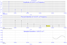
Some JC3 sims made years ago ...
If the 1M FB resistors are omitted, low order distortion remains the same, but high order distortion components rise.
Hi Pavel,
This is what I would have predicted.
Ciao T
If the 1M FB resistors are omitted, low order distortion remains the same, but high order distortion components rise.
This is what I would have predicted.
Ciao T

I do not know whether they are "right". When I compare results of simulated and built amplifiers, the sim results predict real life quite well. Usually the real life THD is 2 - 3x higher than that by simulation, but spectrum shape remains similar.
For this amplifier, the result shown is at less than 10Vp output voltage. In case we go close to 20Vp (for 25V supplies), distortion (simulated) rises to some 0.015%.
For this amplifier, the result shown is at less than 10Vp output voltage. In case we go close to 20Vp (for 25V supplies), distortion (simulated) rises to some 0.015%.
hI,
Pavels Sim looks more like my "modern" suggestion,though the BD139/BD140 are more than bit long in the teeth.
I stand with my original suggestions to answer the question what the local loop does in the JC-3 as originally designed.
Ciao T
so those are "the right" device models?
Pavels Sim looks more like my "modern" suggestion,though the BD139/BD140 are more than bit long in the teeth.
I stand with my original suggestions to answer the question what the local loop does in the JC-3 as originally designed.
Ciao T
"Best sounding" is subjective, so anything goes.
Likely the correct answer is "any, all or none".
Of course it is subjective, that's why I only asked for the OPINION (not FACT) of a certain group of designers (not all of them).
I am not looking for a correct answer (i.e. universally valid) , but for a SUBJECTIVE one (valid only for a small set of people/designers).
...
So I would suggest that "acceptable performance" is one that produces no more than 0.3% 2nd HD and 0.1% 3rd HD at rated power below clipping and less than 0.03% 2nd HD and 0.01% 3rd HD at 1 Watt, with the distortion below 1 Watt behaving monotonic (distortion falls with level) and preferably also above 1 Watt.
...
I am afraid you misunderstood my question: I am not looking for "acceptable performance" but for "acceptable topologies" for the "best sounding" amplifiers. Of course, "best sounding" is a subjective matter, therefore I asked specifically the designers that prefer low of no feed-back topologies.
But thanks for the rest of your detailed post, and for taking the time to write it.
- Status
- Not open for further replies.
- Home
- Member Areas
- The Lounge
- John Curl's Blowtorch preamplifier part II