Not on purpose...I just put up the equations becker had. The R in what I posted is not cable Z, it is resistance per unit length. Apparently, when you use a cable which has lossy conductors, and capacitance with "leakance" to use becker's word, you have to make those two terms equal to minimize damping. Thusly, the result is that the propagation frequency becomes constant across the fequency band of interest. Otherwise, the high frequency content will arrive at a different time from the low frequency content, hence the distortion.
Now it's flux tubes, pinning sites, yada yada..yada...
Cheers, John
John.
I apologize, glancing at the equations you presented, they appear to be the first step in how constant cable impedance became recognized. You did not violate the rules about making things too clear or simple.
The Sullivan papers you pointed folks too are really excellent. I don't think the monosylabic content hits 50%! Of course things only become easy to read when it gets up past 75 to 80 %! Good Job!
Scott,
Do you realize that if thermal eddy currents increase the noise in a transformer that ultimately would lead to "Star Trek" type long range sensors?
ES
Long range sensors - why? The winding is sensing something inside it, not a few light years away.
I think he was joking. In any case that Midcom app-note saves me from the math and as homework I will see if we can use an ohm-meter and noise to characterize L's and get the same answers.
With no coil current, what eddy current losses?If your measurement bandwidth is, say, 10Hz then average over 0.1s. If your core size is, say, 1cm^3 then average over that volume.
Exactly that flux which will induce a voltage in the windings equal to the thermal voltage of the reflected resistance due to eddy current losses.
You and me both, dude... Yours is certainly sufficiently accurate enough for this discussion...Calculating back from the expected thermal power is the easiest way to do it. As the winding encloses the core the issue of flux above the surface does not arise. The engineers' picture of lines of flux cutting a winding may helps with visualisation, but the correct method involves surface and line integrals - a surface integral of the flux threading the winding gives the voltage induced along a line integral around the winding (curl E = dB/dt). However, I must admit that my EM theory is rusty these days.
The surface integral along any cross section of the core will suffice, with charge carriers and thermally induced motion built in.
No, thermal electronic(instead of atomic, my poor choice of words) motion. Remember, it was electrons moving which dissipated the energy so it must be electrons moving which create the noise.
So now, back to the real question we've been "arguing"You keep asserting that there can be no net flux, and keep asking me to provide the mechanism for this. I (and others who know some physics) keep telling you that you are mistaken, and that thermal fluctuations are the mechanism.

How does this sytem "know" that it can produce eddy current dissipation when the entire core is excited at vary large macroscopic flux rate of change. How does atomic level thermal vibrations which cause no eddy currents to exist, show up in the coil edit:differently in laminated vs non laminated structures.? Or, in e/m parlance, how does the introduction of planar conductivity breaks in the core structure (laminations) impact the distribution of electron velocities in the direction parallel to the breaks (edit
such that the surface integral at the coil becomes different. Who knows, I am not counting...How many times do we have to go around this circle?
I don't know what else to say, as you don't seem to understand thermal fluctuations. Please forgive my bluntness.
ARE YOU NUTS??? You have nothing to be forgiven for. Your disagreement has been wonderfully intellectual and stimulating..nothing to apologize for..
I was wondering about the input impedance, as you've loaded the inductor and as a result, pushed coil current through a lossy inductor.
Also, what does the system do with a pure resistor of the same value?
Perhaps it would be good to also run Ls-Rs through the audio band as well? I could do that.
Cheers, John
Last edited:
As usual someone else has done the homework and we can copy it.
http://products.midcom-inc.com/Tech/pdf/tn82.pdf
Excellent link. It must be noted that the choice of Ls-Rs and Lp-Rp is dependent on the ratio between the resistance and the reactance of the coil. The HP manual is very clear in that regard (yah, right...hp manuals are not exactly easy reading..
. Some xfmrs may be better modelled one way or the other..That's better. insulting me will get you nowhere..You did not violate the rules about making things too clear or simple.
Hey, thank him, not me... I learned about him years ago when he wanted me to do some things for him..didn't pan out, but man, the guy's the 800 lb gorrilla in the room!The Sullivan papers you pointed folks too are really excellent. I don't think the monosylabic content hits 50%! Of course things only become easy to read when it gets up past 75 to 80 %! Good Job!
Cheers, John
Oh dear, here we go again! The eddy current losses which are present with a signal give rise to a resistance reflected into the primary winding. You can measure it. The resistance remains even when there is no signal, because the mechanism is still present. Does your car disappear when you are not driving it? Does your cup disappear when you are not drinking coffee?jneutron said:With no coil current, what eddy current losses?
Each lamination acts like a tiny loop, with some resistance. When driven. this is where the eddy current losses occur. The loop is still there, with its same area and resistance, when not driven. The random thermal motion of electrons average out to zero, as you say, when averaged for an infinite time. Over any shorter time, there will sometimes be a net clockwise rotation of electrons around the loop, sometimes anticlockwise. That is what random means - if they averaged to zero over any time period (as you claim) they would not be random! A change in lamination thickness changes the size of the loop, and hence the area, but hardly changes the resistance. The area changes the flux, for a given random current flow - bigger area, bigger flux.
Oh dear, here we go again! The eddy current losses which are present with a signal give rise to a resistance reflected into the primary winding. You can measure it.
Again, that is precisely what I have said multiple times. We have all agreed to that for a thousand or so posts.
Rotation requires a magnetic field. You are now saying that thermal motion of electrons in the core can rotate? Other that electron-electron or electron/nucleus interaction (bremsstrahlung), where is the gross, macroscopic magnetic field which curves the path coming from? When a flux derivative intrudes, there are direct loop voltages (gradients) to force curved paths..but the assumption that there can be random, net rotation, is unsupported as of yet..Over any shorter time, there will sometimes be a net clockwise rotation of electrons around the loop, sometimes anticlockwise.
Eddy currents are caused by the macroscopic rate of change of field going through the media. The long loop paths are worse, thin lams interrupt the size of the loop paths.
You have not demonstrated how the interruption of the planar conductivity will cause the coil to pick up less signal. Yes, you understand eddy currents as they are caused by an externally generated field, but your argument on the coil being able to discern the difference between lamination thicknesses based on core thermal energy is just not there. Sorry.
Cheers, John..
ps..shroedinger's car and coffee??
The key word is random. Random not only means that sometimes they go left, and sometimes right, but sometimes they go round. Not like an electron in a magnetic field. I mean the currents go round, not the individual electrons. If an electron at the top happens to go right, and another electron at the bottom happens to go left, then the net effect is a clockwise current. An instant later the current may, or may not, go round the other way.
Think random. That means all possible net movements happen, provided you don't average for too long. What about the next lamination? That is doing the same thing. Won't they all cancel each other out. No, on the contrary, each one contributes a little thermal power.
Think random. Most people don't really understand random, but they think they do.
The key word is random. Random not only means that sometimes they go left, and sometimes right, but sometimes they go round. Not like an electron in a magnetic field. I mean the currents go round, not the individual electrons. If an electron at the top happens to go right, and another electron at the bottom happens to go left, then the net effect is a clockwise current. An instant later the current may, or may not, go round the other way.
Ok...then integrate it.
Do a sectional integration of current for n laminations which add to the total core thickness.
Start at n=1, work your way to atomic level.
Show how it makes a difference what N is to what the coil sees.
It doesn't, for thermal processes.
It does for externally induced rate of change magnetic excitation.
Won't they all cancel each other out. No, on the contrary, each one contributes a little thermal power.
Which of course, makes no difference to the coil.
As I've said, you've not demonstrated a mechanism which creates a coil voltage from the thermal excitation of the core. Until you do, your theory is just that...a theory.
There are non reversible processes in this world...it doesn't end it..
Think random. Most people don't really understand random, but they think they do.
That's just a random thought...
Have a nice evening..
Cheers, John
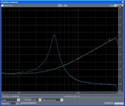
OK, I built the JFET buffers (2SK369's) so the head is unloaded. Much nicer results. This was easier than I thought, after resonating the inductance with two caps I found the L is basicly unchanged so we can ignore that half. It was .048H BTW. I then followed the proceedure in the Melcore app note (BTW they make one of the better xDSL transformers) and found the relationship, Rs = 385 + 1982(f/10k)^1.25 fits the data nicely. This is much worse than the typical audio coupling transformer (.35-.45 power of f).
The picture shows the unloaded noise and the noise head resonated with 33nF of capacitance.
My line of reasoning, at low f the noise is asymtotic to 385 Ohms on both plots and at the high end on the L/C resonance plot it is asymtotic to the preamp rti noise. From this I computed the preamp to be 1.87nV, reasonable. From this I computed the resistance from the noise at 10kHz and subtracted the 385 Ohm series resistance. I then fit the data and equation with a couple of iterations of lying them on top of each other.
So there you go JC you were right, eddy losses are a much bigger problem on tape heads than coupling transformers.
JN I drink it black.
Attachments
Last edited:
Out of time, quick correction the plot is with the 8.2nF cap so the head inductance was .193H, the exact value of L falls out anyway unless we do the parallel/series transformation.
My SPICE lets me enter an equation for R vs f in a noise analysis but the answer is garbage, so I will need to step one f at a time to verify the shape of the resonant plots.
It was Midcom not Melcore too, jeez. BTW out of the blue Monday I got an email from the CTO of Bose asking an op-amp question, considering last weeks conversations I laughed (the customer is always right goes both ways).
Last edited:
Very nice, thanks..OK, I built the JFET buffers (2SK369's) so the head is unloaded. Much nicer results.
Questions..
1. When you unloaded the head, what was the difference in the noise profile?
2. Can we state that loading the head created more eddy current losses as a result of the loading current? Is it worse. Or, is that not discernable given the data.
Now, given the setup, do you think it will be useful for doing the 4 core test? Where we can really determine the overall effect by changing the eddy current possibility?
edit: After thinking more about it, I still believe driving a sine and looking for sidebands is more consistent with examination of eddy effects. I can do some testing on the HP LCR if it'll help..
JN I drink it black.
So Scott...why do I owe you a cup of coffee? Not tryin ta weasel out mind you. But I've all along been clear in that I consider John C's assertion as valid..
I have some really good zip loc bags, I'll put the coffee (black of course) into it (piping hot), double it up, put some of those wheat based peanuts around it case you need a snack as well.... and send it to ya...gonna need an addy of course.
Mind you, given the speed of the USPS, I can't guarantee it'll be hot when it arrives...
Or, y'all could just visit me sometime...give me a holler anytime you're in the area...I'll give you the 10 cent tour and a free cup of java..saves on my postage...hey, might even be able to show you how an antimatter confinement bottle is made...really neat, trust me...
Cheers, John
Last edited:
Very nice, thanks..
Questions..
1. When you unloaded the head, what was the difference in the noise profile?
2. Can we state that loading the head created more eddy current losses as a result of the loading current? Is it worse. Or, is that not discernable given the data.
Now, given the setup, do you think it will be useful for doing the 4 core test? Where we can really determine the overall effect by changing the eddy current possibility?
edit: After thinking more about it, I still believe driving a sine and looking for sidebands is more consistent with examination of eddy effects. I can do some testing on the HP LCR if it'll help..
The noise profile was screwed up a lot, I didn't know the mic pre was only 6k (it usually sees 200 Ohms). This makes the problem like telling the difference between 6K and 6.5K only measuring noise. The 4 core test should work fine and I'll get right on the sine test as soon as I get my generator repaired. I will check a mike input transformer, though I don't have a phono one around. I also should verify the results with my GR impedance bridge at at least a couple of frequencies too.
This stuff is fun and I hope folks can take away an understanding of just how much we do know or can find out. Always love your posts and would love to visit, pass on the baggie of coffee.
BTW this thread has worked up to 6 or 8 on Google for info on eddy current loss.
Last edited:
Nothing like a little real data to send folks back to the cable treads. Sigh. The principle of the kaka magnet.
Well, I'm impressed. As you say, with some dilligence and willingness there's very little you guys can't peel away. I love it, wish I was that smart.
BTW Those graphs you show, are they from that low-cost digital scope?
BTW-2 Vol 1 just ran off the press. I'll get you a copy.
jan didden
Nothing like a little real data to send folks back to the cable treads. Sigh. The principle of the kaka magnet.
You could at least sneer a little more.
If you want some high quality phono or mike transformers as victims, let me know.
This stuff is fun and I hope folks can take away an understanding of just how much we do know or can find out.
As well as how much we do not know. The temp noise vs eddy loss structure being a good one. It remains to be seen if I am correct or incorrect on my stance..but as I stated earlier, the destination is not as important as the journey.
Always love your posts and would love to visit, pass on the baggie of coffee.
Bummer, I was starting to wonder if a freezer bag of coffee would have made it.. Problem is, if the bag broke in transit, it'd probably involve homeland security. A while ago I was thinking of sending Jon R a gallon of moosetrack ice cream, insulated to smithereens and a starting temperature of 77 Kelvin.. Never did it though...
If you ever make it, I'll probably ping ya for some IC's..apparently we've designed some stuff that's in short supply for our first article widgits.
Interesting. I wonder if it's just from the guys here looking for info?BTW this thread has worked up to 6 or 8 on Google for info on eddy current loss.
Cheers, John
Last edited:
Scott thank you for your work.
Can you describe your measurement set-up in some detail? I plan to do some measurements in a week or so on some small x-formers I bought for experimentation.
Also on tn82.pdf, you linked to, on page 7 at the Rcf equation, the f/fr bracketed, is it raised to a power?
Regards
George
Can you describe your measurement set-up in some detail? I plan to do some measurements in a week or so on some small x-formers I bought for experimentation.
Also on tn82.pdf, you linked to, on page 7 at the Rcf equation, the f/fr bracketed, is it raised to a power?
Regards
George
The bigger picture on noise
I've been following this interesting part of the thread on noise sources in things like MC step-up transformers, but may have somewhat lost sync with the original objective of the discussion or how it got started. Maybe someone can set me straight.
I think the context is largely noise in MC preamps using step-up transformers as opposed to a solid state head amp. Is that correct?
Was someone arguing that step-up transformers are not necessarily better noise-wise than a solid state approach because of transformer noise?
If this is all true, here is what I would like to see, unless I have missed it.
What is the input-referred noise at 1 kHz of a given head amp (like John's), feeding John's RIAA phono preamp in nV/rt Hz?
We just take the noise spectral density at the output of the phono preamp at 1 kHz and divide it by the voltage gain that exists at 1 kHz from the MC cartridge to the phono preamp output. A given MC cartridge is assumed.
Similarly, for comparison, what is the input-referred noise (referred to the MC cartridge), at 1 kHz, for a step-up transformer feeding John's RIAA phono preamp?
Wouldn't that comparison help answer the underlying noise question (assuming I've got the question right)?
Finally, in the context of this noise discussion, it seems that we need to keep the issue of noise in context with all the other performance characteristics of the phono preamp setup. Once noise gets below a certain point, it may not matter much in comparison to other issues affecting sound quality. If we focus too much on noise, I don't think that can be optimal.
For example, we know that the noise of John's head amp is very low. Even if a transformer was used and noise was better by a couple dB, who cares?
Cheers,
Bob
Bob: For a bipolar input, the input xfrmr will probably not be optimum since noise figure is minimized at Rsource = en/in. For FETs and tubes, the transformer will almost certainly give a noise advantage for low Z MCs- in fact, it can reduce the need for massive paralleling. The issue of CMR is another reason why one would want to go that route.
John C has speculated that there's an intractable LF noise source in step up transformers. I haven't seen that in actual MC amp noise measurements, but the Smart Guys are now doing some other measurements to see if it's plausible and under what circumstances it COULD be significant.
John C has speculated that there's an intractable LF noise source in step up transformers. I haven't seen that in actual MC amp noise measurements, but the Smart Guys are now doing some other measurements to see if it's plausible and under what circumstances it COULD be significant.
- Status
- Not open for further replies.
- Home
- Member Areas
- The Lounge
- John Curl's Blowtorch preamplifier part II