I am going to REMOVE the transformer.
So you're going to trade some low frequency distortion for poorer noise performance?
se
From the conclusion of the Marshall Leach article someone posted Noise Analysis of Transformer-Coupled Preamplifiers "In the case of a JFET input stage, the examples predict better noise performance with the transformer, but the improvement is not large." Also: "It is shown by example that the optimally biased BJT input stage can have less noise when a transformer is not used."
.
.
Last edited:
Johnferrier, with all due respect to the late Marshall Leach, the article was more academic than practical.
He did not even appear to note the popularity of Toshiba devices or that paralleling jfets lowers the noise in the same way as a transformer does. I am already paralleling 8 jfets on each input leg of the input stage, so my self noise is pretty small in any case. ALL I have to do is to change the input devices to something 3dB quieter, and I can achieve just about anything that I might get with a transformer, perhaps being 3dB off from worse case with a virtually ideal transformer.
However, transformers are NOT ideal. They have both DC and AC resistance that limits their potential, AND they either distort at low frequencies and have an excellent midrange sound quality, OR they don't distort as much at low frequencies, BUT everybody who cares about such things, says they don't sound as good in the midrange. I got this DIRECTLY from the Lundahl rep at the AES-SF in front of the transformer designer, himself. What to do? Better to eliminate the complexity of the SOMETIMES used transformer, removing several relays, shortening the input path length, save the money for better fets, and have a virtually pristine thru-path. So far as I know, the decision has been made. You see, for $50 extra dollars in jfets, I can get almost the same S/N and save about $250 per channel by removing the transformers and relays. I just saved my company at least $400 OEM. WOW! Maybe we can now sell it at $38,000 or maybe they will give me a bonus. '-)
Last edited:
This has more to do with hysteresis.
Driving amorphous core transformers (which have very little hysteresis compared with silicon steel transformers) with low source impedances like MC cartridges will have virtually no non-linear distortion of importance.
John's measurement at 10 Hz of the two step-up transformers with such different results is not a hysteresis matter but, once again, points in the direction of core saturation.
I am still curious after John's measurement set up, especially at which amplitude the 10 Hz measurement was done. John still there?
The following is a quote from the link I posted here (thanks Pano
") : http://www.diyaudio.com/forums/analog-line-level/146693-john-curls-blowtorch-preamplifier-part-ii-1114.html#post2501525
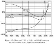
: http://www.diyaudio.com/forums/analog-line-level/146693-john-curls-blowtorch-preamplifier-part-ii-1114.html#post2501525But in a real transformer design there is a fixed relationship between signal level, distortion, and source impedance. Since distortion is also a function of magnetic flux density, which increases as frequency decreases, a maximum operating level specification must also specify a frequency. The specified maximum operating level, maximum distortion at a specified low frequency, and maximum allowable source impedance will usually dictate the type of core material which must be used and its physical size. And, of course, cost plays a role, too.
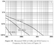
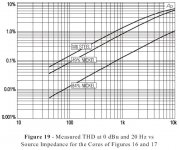
The most commonly used audio transformer core materials are M6 steel (a steel alloy containing 6% silicon) and 49% nickel or 84% nickel (alloys containing 49% or 84% nickel plus iron and molybdenum). Nickel alloys are substantially more expensive than steel. Figure 17 shows how the choice of core material affects low-frequency distortion as signal level changes. The increased distortion at low levels is due to magnetic hysteresis and at high levels is due to magnetic saturation. Figure 18 shows how distortion decreases rapidly with increasing frequency. Because of differences in their hysteresis distortion, the fall-off is most rapid for the 84% nickel and least rapid for the steel. Figure 19 shows how distortion is strongly affected by the impedance of the driving source (the plots begin at 40 Ù because that is the resistance of the primary winding).
It seems that pieter t knows well what he is talking about and no one is to accuse him .
OK,
As quick as I popped in here so quick will I pop out.
When you guys, reputations or not, don't take the effort to give proper replies I don't put more time in this; enough other things to do
It is 1 AM here, good night.
Regards
George
Attachments
Last edited:
Once again a flawed conclusion. All we know is that in the test that was performed, tranformer A outperformed transformer B. We don't know why and we don't know what other results might still make transformer B a better choice. Was the distortion in transformer B the result of the lack of laminations, the particular alloy used in the core, or some other factor such as the way the transformer was wound? Or a combination of them? Is the drive level realistic for an MC cartridge? What other performance results would be obtained if we measured FR for example? What about input/output linearity especially at very low signal levels where initial coercivity of the domains could be quite different. Wrong conclusion because it is based on insufficient data to completely describe all factors influencing transformer selection and typical of how tinkerers think. Then when transformer B "sounds better" than transformer A, audiophiles dismiss the value of making any measurements at all because they don't correlate to what they hear. Junk science.
Once again a flawed conclusion. All we know is that in the test that was performed, tranformer A outperformed transformer B. We don't know why and we don't know what other results might still make transformer B a better choice. Was the distortion in transformer B the result of the lack of laminations, the particular alloy used in the core, or some other factor such as the way the transformer was wound? Or a combination of them? Is the drive level realistic for an MC cartridge? What other performance results would be obtained if we measured FR for example? What about input/output linearity especially at very low signal levels where initial coercivity of the domains could be quite different. Wrong conclusion because it is based on insufficient data to completely describe all factors influencing transformer selection and typical of how tinkerers think. Then when transformer B "sounds better" than transformer A, audiophiles dismiss the value of making any measurements at all because they don't correlate to what they hear. Junk science.
I agree with this.
Well Pieter, I still don't know if you can do better, or would I have to live with a good amount of harmonic and subsequently IM distortion using one of your transformers. That was the question, and I spent some real lab time answering your question. No hard feelings, except that it is easier for me to not use a transformer in the first place. I can get 10 ohms equivalent noise, in any case, if I choose another jfet, that I have many hundreds of.
It is true that the transformer is not a bad solution, just a 'mixed' solution and not inexpensive either.
Sorry, if my abrupt manner offended you, but I was trying to get YOUR numbers, not re-generate another company's distortion comparison.
It is true that the transformer is not a bad solution, just a 'mixed' solution and not inexpensive either.
Sorry, if my abrupt manner offended you, but I was trying to get YOUR numbers, not re-generate another company's distortion comparison.
Well Pieter, I still don't know if you can do better, or would I have to live with a good amount of harmonic and subsequently IM distortion using one of your transformers.
... according to Mr. Jensen, your worry about IMD may be misplaced.
"...note that distortion for 84% nickel cores roughly quarters for every doubling of frequency, dropping to less than 0.001% above about 50 Hz. Unlike that in
amplifiers, the distortion mechanism in a transformer is frequency selective. This makes its IM distortion much less than might be expected. For example, the Jensen JT-10KB-D line input transformer has a THD of about 0.03% for a +26 dBu input at 60 Hz. But, at an equivalent level, its SMPTE IM distortion is only about 0.01% — about a tenth of what it would be for an amplifier having the same THD".
...from http://www.jensen-transformers.com/an/Audio%20Transformers%20Chapter.pdf
not exactly MC xfmr candidates - and you conflate with a statement about typical signal level audio interconnects from SE's post
and somehow adopt my point as your objection???
I have no idea what you just said. Re-try please.
again you accept that core (and winding proximity/skin) eddies are coupled by mutual inductance to the windings but don't recognize the model validity of the secondary connected to a R??
You proposed a physics model where heating of the core will produce voltage at the terminals.
Not heating of the coil, but the core.
You are proposing a violation of a non-reversible process, one that will indeed violate the law....
Thermal molecular energy in a core will not produce a magnetic field which couples to a coil.
Cheers, John
ps..away two days...sheesh, what a thread...
Thermal energy in the core will jiggle electrons. Moving electrons create a magnetic field. The coils will be coupled to this field. I don't understand your apparent denial of this.Thermal molecular energy in a core will not produce a magnetic field which couples to a coil.
As a general principle, a dissipation mechanism is also a fluctuation mechanism. Do you dispute this? Are you confusing the fact that the time averaged magnetic field will be zero, with the fact that the time averaged field-squared will be non-zero?
He pointed out the lack of data presented, and the consistency of this occuring.SY, SY, SY...
This got interesting, based on technical opinions. The issue is minor and reasonably well discussed. If you don't believe J.C. that is not a technical issue. You can either confirm it, or disprove the content of the call, but personal issues really don't belong here.
ES
Thanks. it is indeed intellectually stimulating..This is fun. Some homework, I don't have access but I think this will shed some light... Phys. Rev. 105, 896 (1957): Thermal Fluctuations in Conductors
As far as core losses are concerned: Quote without comment.
"Then if an eddy-current loss of 6dB is acceptable at 16kc/s (Hz) the lamination thickness must not exceed 6 mils, and for the same loss at 600Kc/s it must not be more than 1 mil." p.50 'A Survey of Factors Limiting the Performance of Magnetic Recording Systems'
JAES, Jan. 1957 E. D. Daniel et al. Most authors were with the BBC. Daniel was with National Bureau of Standards, Wash. D.C.
Hopefully you will get a copy and believe what they say. Equations are provided, on a previous page.
Nice, thanks.. Any papers from this century?
This kind of talk is a complete rejection of the mathematical principles of Fourier which leaves no room for doubt that response beyond 20 khz serves no useful purpose.
Perhaps. But humans discern 2 to 5 uSec interchannel, bw limiting to 20Khz eliminates some of what we use..
If I had the option, I'd take it to 500 Khz despite the fact that I can't hear 20k and the drivers can't reproduce it.
No, that is the whole point I am trying to make. The mechanism exists anyway. The random thermal fluctuations in the core sum do not sum to zero, but sum to a thermal energy - just like a resistor. They generate a field which induces a noise voltage in the windings.
Individual atoms themally moving may. But the integrated core produces no magnetic field which will couple to the coil.
Transformers with identical windings, but different degrees of coupling to eddy currents in the core, will give different thermal voltages. You can calculate the thermal voltage by first measuring the resistance at a particular frequency - this will be greater than the DC resistance.
That is actually my point. But it is not a result of the temperature of the core. I think that is being confused here.
That is why I devised the hf driven scenario with different cores.
I agree.Sorry to drag us back to this point, but I think this is still not understood by some in this debate.
google "mean free path".To try to settle another point, current in an ordinary wire does not generate shot noise. How do we know this? Well, for a start how could we measure shot noise in a valve (which is much smaller than sqrt(2ei)) if the wires attached to the valve contributed even more shot noise too? No, in a wire the electrons can 'see' each other so their flow is correlated - they behave in a similar way to a classical gas.
I think it's too far out. LSI chips would have a big problem given the SiO2 thicknesses involved.I now want to toss in a new thought. Is it possible that the insulation between laminations may permit some electron tunneling - it is very thin. If so, this may be a source of shot noise which would be signal dependent. I have no idea what the magnitude might be, so this could be a red herring.
Steve,
One of the demos we do around here is to play a 30,000 cycle per second sine wave through an old Spica speaker. Everyone says they don't hear any thing. Then I turn it off and just about everyone realizes they can detect it going off and then back on. It does not sound like a clean tone but the energy is certainly perceived.
You are correct. The energy is perceived. If you very carefully experiment, you may find that they perceive a reduction in background noise when the 30k is on. The inner ear is backing the gain down...
Interestingly enough, an air gap is where the bulk of the mag energy is. (tidbit only, not discussion worthy..)That's probably because Per isn't using cut cores in the LL1931.
That means no air gaps, which means higher efficiency (more like a toroid which also doesn't have an air gap). That means that all else being equal, it will saturate sooner than a laminated core or a cut C core.
se
Cheers, John
Let's break this one out, shall we?Thermal energy in the core will jiggle electrons. Moving electrons create a magnetic field. The coils will be coupled to this field. I don't understand your apparent denial of this.
1. Thermal energy in the core will jiggle electrons. Agreed.
2. Moving electrons create a magnetic field..again, agreed.
3. The coils will be coupled to this field. Here's the point of contention.
Thermal motion of electrons within a core are not unidirectional, they will be totally random. The random movement of huge quantites of free electrons will not produce an external time varying magnetic field in a core which can couple to a coil.
The coil is sensitive to time varying flux (ala faraday) passing through the coil. Thermal motion of the core does not produce a time varying flux within the core on the macroscopic level, as there is no motion coherence.
Cheers, John
Let's break this one out, shall we?
1. Thermal energy in the core will jiggle electrons. Agreed.
2. Moving electrons create a magnetic field..again, agreed.
3. The coils will be coupled to this field. Here's the point of contention.
Thermal motion of electrons within a core are not unidirectional, they will be totally random. The random movement of huge quantites of free electrons will not produce an external time varying magnetic field in a core which can couple to a coil.
The coil is sensitive to time varying flux (ala faraday) passing through the coil. Thermal motion of the core does not produce a time varying flux within the core on the macroscopic level, as there is no motion coherence.
Cheers, John
If it would work, the core would drop in temp if the coil was shorted. No?
jan didden
If it would work, the core would drop in temp if the coil was shorted. No?
jan didden
Yup. Load the terminals, quantum refridgeration.
That's why I said (about a thousand posts ago on friday) I'd love to see( (edit) :stockholm) and da king..
Cheers, John
You'll have to share the prize with the fellow who suggested that energy flux was the key.
Share??? SHARE????
Never I tell ya...never.
Sides, I got's my capacitor for storing the flux...
Cheers, John
Your point of confusion is what I suspected it to be. If you apply your reasoning to a resistor, then you would prove that a resistor cannot generate a thermal voltage as there is no net movement of electrons there either.Thermal motion of electrons within a core are not unidirectional, they will be totally random. The random movement of huge quantites of free electrons will not produce an external time varying magnetic field in a core which can couple to a coil.
The coil is sensitive to time varying flux (ala faraday) passing through the coil. Thermal motion of the core does not produce a time varying flux within the core on the macroscopic level, as there is no motion coherence.
Taken over an infinite period, there is no net movement. Taken over any finite period, there is some net movement. The shorter the period (i.e. the wider the bandwidth) the greater the movement. That is why you get more noise in wider bandwidths.
A perfect short could not dissipate any heat so no. A resistance would extract heat from the core, but would contribute its own thermal energy so you end up with equilibrium. This is the point of Nyquist's paper, cited above.If it would work, the core would drop in temp if the coil was shorted. No?
I have no need to Google mean free path. Scattering of electrons might produce some noise, but that would not be shot noise. In a good conductor the electrons spend most of their time not being scattered - that is why it is a good conductor.
I think I need to provide a little more detail on what I've been discussing..
From wiki:
""However the "excess noise" of a practical resistor is an additional source of noise observed only when a current flows through it. This is specified in unit of μV/V/decade - μV of noise per volt applied across the resistor per decade of frequency. ""
My use of the term shot noise is probably mixing it up, so I looked for and copied this from wikipedia..
My discussion centers around this particular effect, one of "put in current", noise increases..
My concern is that at DC, the primary coil will have a resistance. Measurement of the excess noise voltage at a specific DC current uses the full conductor cross section, so uses the actual winding resistance.
If one forces AC current into the primary, one cannot expect the use of the full cross section of a larger conductor because of proximity effects. My expectation is that the excess noise will be proportional to the effective series resistance of the coil. This is what my HP4284A actually measures.
So, if the series resistance of a coil increases two orders of magnitude at the driven frequency, I would expect the excess noise to increase accordingly.
Now, for John Curls "assertion"..I have measured the increase in coil resistance at frequency as a direct result of eddy current dissipation, both within a laminated structure as well as with amorphous materials such as brass, aluminum, and stainless.
So I firmly believe that John's assertions are accurate. I also agree that measurement of Q will indeed relate to this effect.
It would be great if somebody put tests together to specifically show this.
I'd love to assist where possible..
Cheers, John
- Status
- Not open for further replies.
- Home
- Member Areas
- The Lounge
- John Curl's Blowtorch preamplifier part II