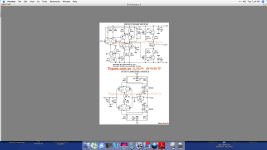
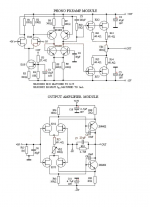
I indirectly copied the general topology for the phono preamp module for the Levinson JC-2 phono stage in 1973. However, Matti Otala's philosophy taught me that another circuit configuration might be even better, so became the line stage module for the JC-2. I still use this design today. Being a creative engineer does not necessary apply that his designs sound the best.
Attachments
Scott, Billshurv, when he criticized your interest in the Audio Palette.
I had no idea Dick had anything to do with this, OTOH as it was pointed out Mr. Iverson was caught in an out and out lie. Thanks for posting the 40yr. old schematics again brings back last month's memories.
I knew John Iverson pretty well as well. I went to Japan with him and an Audiophile/investor type to meet with Honda on a scheme for much more efficient generators. He had many interesting ideas, but an all too common outsized ego, a bit of pugnaciousness and not to willing to confront his errors. I think those qualities may be necessary for success as an audio entrepreneur. We both let the preamp issue pass as part of an ill conceived marketing effort. I think he made maybe 10 of those preamps.
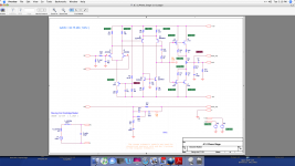
Here is the input ckt. of contemporary HP audio band power amp (Well DC to 1 MHz actually) showing some of the same concepts. The upper circuitry is the HF amplifier that runs in parallel with the DC/low frequency amp. .01% THD at 1 KHz full load for 1965. A lot of this is skilled designers working with the limitations of the available technology. I have one and at 50+ years its still working to spec. with the original parts. I'm sure a cap upgrade would be a good idea but a lot of effort.
Attachments
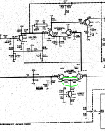
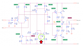
Kind of a surprise to see that C2 is only 39pF, and to notice where its bottom plate is connected.
Impedance at the base of Q3 is about 250 ohms, so C2 becomes effective at frequencies above 16 MHz.
_
I may be confused, but even with the diode connection, the differential pair it seems to me would raise the node impedance to dynamic signals.
I can't specifically remember why that cap was necessary, but then I designed it in 44 years ago. I am pretty sure that it is to partially compensate the parallel path that does not have the primary comp cap.
In those days, especially me, we used cut and try, or a calculator to make design decisions. I suspect I might be able to find why this cap in my class notes from Cal Berkeley that I recently took, but I would have to look it up. For the record, SPICE was very new at the time, and I did not use it for this design.
In those days, especially me, we used cut and try, or a calculator to make design decisions. I suspect I might be able to find why this cap in my class notes from Cal Berkeley that I recently took, but I would have to look it up. For the record, SPICE was very new at the time, and I did not use it for this design.
Not really since the collectors of the PNP differential pair are current sources with very high impedance. A high impedance in parallel with a low impedance, is a slightly lower impedance.I may be confused, but even with the diode connection, the differential pair it seems to me would raise the node impedance to dynamic signals.
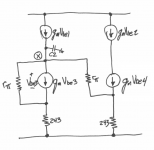
Looking into the base of Q4 we see (Beta * Rexternal) = (200 * 243) = 48K
Looking into the base+collector of Q3 we see ((1/gm) + 243) = 251 ohms
(48K || 251) = 249.7 ohms. So, about 250 ohms.
Oh by the way, SPICE gets the same answer.
Let's have a little fun with worm-cans. Suppose the gain at 1 kHz really is 32.8dB as the attachment to post #94067 suggests. Further suppose that C2 does something useful before the unity gain crossover frequency. Then unity gain crossover > 16 MHz and therefore open loop bandwidth is greater than (16 MHz / 32.8dB) = 368 kHz. That's a pretty good-sized OLB. (If silly assumptions A and B above, are correct)
Are you OK with the bottom plate connection?
_
Attachments
Last edited:
That's a pretty good-sized OLB.
_
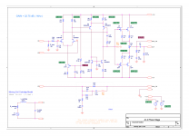
With this like most op-amps it's trivial to first order cancel the the output impedance of Q2, Q4, and R31 by a small amount of positive feedback from the output to R3 and R4. Then looking at it as a 5 pin black box you have a 10 or 100Hz OLBW, doesn't make one jot of difference though. High OLBW is a meaningless metric.
Easy to sim, easy to build, the low amount of feedback has no stability implications at all BTW.

The schematic was designed with a mistake.
Called it!

I've seen a lot of mistakes like this, although at first I wanted to believe it was for PSRR improvement.
- Status
- Not open for further replies.
- Home
- Member Areas
- The Lounge
- John Curl's Blowtorch preamplifier part II