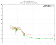
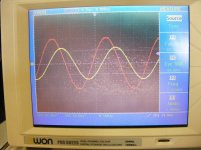
While I'm at it, that's the noise I get from 16 BF862 at 44 mA tot., cascoded
with ZTX851, Post amps = ada4898, Bias servo with opa2143.
Servo still needs some work.
Red trace is 60 Ohm thermal noise = 1nV rtHz, green is input shorted.
10 dB below 1nV, or about 320pV rtHz.
The same board can be populated with 2*IF3602, not yet tested.
with ZTX851, Post amps = ada4898, Bias servo with opa2143.
Servo still needs some work.
Red trace is 60 Ohm thermal noise = 1nV rtHz, green is input shorted.
10 dB below 1nV, or about 320pV rtHz.
The same board can be populated with 2*IF3602, not yet tested.
Attachments
Last edited:
While I'm at it, that's the noise I get from 16 BF862 at 44 mA tot, cascoded
with ZTX851, Post amps = ada4898, Bias servo with opa2143.
Servo still needs some work.
Red trace is 60 Ohm thermal noise = 1nV rtHz, green is input shorted.
The same board can be populated with 2*IF3602, not yet tested.
I see the FFT "stitching" is that bump at ~20Hz real or an artifact? I await the IF3602 measurements, I have 5 in the bin.
It is one FFT per decade, corrected for bandwidth, from an Agilent 89441A signal
analyzer. The decades have been stitched together by gnuplot that is fed from a
C program under Linux that controls the 89441A via LAN.
Input coupling is 10u foil * 4*47Meg, probably temporarily less because the
settling time stresses my patience.
Disregard the stuff below 20 Hz, the 1/f corner is a KHz or so.
Also the total gain seems to be one dB low. (only 79, not 80 dB)
Gerhard,
Very impressive.
However as you and I are using similar tools to look at quite different issues, I will drop the quick results of my latest playing around.
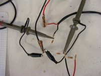
I took a 50' piece of 16 gauge loudspeaker wire. Terminated one end with a 10 ohm resistor. Fed the input through a 1 ohm resistor to monitor the current through the cable. Also put a shunt across 1 wire with a 1 ohm resistor. At low frequencies the voltage drop thus the current through both resistors (short path vs through the cable) was the same. As the frequency increased the current through the shorter path decreased. Around 2K the short path was 3 dB. down!
JN will have fun with this.
Very impressive.
However as you and I are using similar tools to look at quite different issues, I will drop the quick results of my latest playing around.
I took a 50' piece of 16 gauge loudspeaker wire. Terminated one end with a 10 ohm resistor. Fed the input through a 1 ohm resistor to monitor the current through the cable. Also put a shunt across 1 wire with a 1 ohm resistor. At low frequencies the voltage drop thus the current through both resistors (short path vs through the cable) was the same. As the frequency increased the current through the shorter path decreased. Around 2K the short path was 3 dB. down!
JN will have fun with this.
Attachments
Last edited:
That's a no-brainer. Therefore, I am eminently qualified to answer.Gerhard,
Very impressive.
However as you and I are using similar tools to look at quite different issues, I will drop the quick results of my latest playing around.
I took a 50' piece of 16 gauge loudspeaker wire. Terminated one end with a 10 ohm resistor. Fed the input through a 1 ohm resistor to monitor the current through the cable. Also put a shunt across 1 wire with a 1 ohm resistor. At low frequencies the voltage drop thus the current through both resistors (short path vs through the cable) was the same. As the frequency increased the current through the shorter path decreased. Around 2K the short path was 3 dB. down!
JN will have fun with this.
")
The short path has the inductance of the loop of the black wire, an air core inductor of about 14 turns and 8 inches or so in diameter.
The current through the cable pair has inductance of about .2 nH per foot.
John
That's a no-brainer. Therefore, I am eminently qualified to answer.
The short path has the inductance of the loop of the black wire, an air core inductor of about 14 turns and 8 inches or so in diameter.
The current through the cable pair has inductance of about .2 nH per foot.
John
We just gotta disagree. I think it is the inductance of the red wire. But do note the cable is "counter coiled." (First loop one direction, second reversed.) Putting a bit of steel in the middle of the loop seems to have no effect.
(Sidebar for extra points! How much inductance is required to cause the drop shown?)
Then there is the capacitance causing more phase shift with increasing frequency.
Next up is to run HF bursts through the cable, but first I have to rig up the right test equipment.
Disregard the stuff below 20 Hz, the 1/f corner is a KHz or so.
I only asked because your 1-10Hz looked perfect and would extrapolate nicely down to the 100-1k plot, just the 10-100 looks anomalous. I once did one of these plots down to 10uHz to prove GR noise just hides 1/f. One of the disagreements I had with the LIGO guys was that one should be able to make FET's with .001Hz corner frequencies, I'm not sure any current structure would support that.
We just gotta disagree. I think it is the inductance of the red wire. But do note the cable is "counter coiled." (First loop one direction, second reversed.) Putting a bit of steel in the middle of the loop seems to have no effect.
(Sidebar for extra points! How much inductance is required to cause the drop shown?)
Then there is the capacitance causing more phase shift with increasing frequency.
Next up is to run HF bursts through the cable, but first I have to rig up the right test equipment.
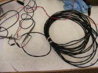
Your coil of cable does not match your description of "counter coiled".
Second, no schematic.
Third, you look to be confounding the short current measurement with the CVR.
Fourth, what is a "bit" of steel, and how sensitive do you think the breakpoint would be to a fractional increase in inductance and a fractional increase in series resistance? Remember, your coupling to a "bit" of steel isn't going to be very good, as the gap between the steel and loops is the very definition of "parasitic inductance", and it is that parasitic inductance that you are seeing.
Your setup is entirely uncontrolled and undocumented. Again, this is a common theme of yours I bash you for.
Thanks for the opportunity to again bash you for your lack of clear methodology and scientific rigor.. I missed that.
I'm actually starting to do things again, working on an indexing fixture for some clock work.. and looking at my pile of 132 4 inch drivers...and 200 tweeters..with the router bits in hand...I was thinking maple for the front of the line arrays...
John
I'm actually starting to do things again, working on an indexing fixture for some clock work.. and looking at my pile of 132 4 inch drivers...and 200 tweeters..with the router bits in hand...I was thinking maple for the front of the line arrays...
John
Dude, NC. (Unless you're SERIOUSLY looking to avoid people for a very_long_time.
) And solid wood of that size makes me nervous from dimensional stability perspective.Carry on. Shouldn't need much more than a NE5532 or 2 to power that setup to deafening levels.
Dude, NC. (Unless you're SERIOUSLY looking to avoid people for a very_long_time.
Carry on. Shouldn't need much more than a NE5532 or 2 to power that setup to deafening levels.
It's called therapy. Definitely in need of that.
As to stability, the structure will be well designed and braced. Also, I like to seal the woods to prevent moisture movement.
I'm designing it so that I can parallel 6 arrays of 10 4 inchers 18 by tweet on each side of the amplifier. 12 panels on my rmx1450 will pull close to 1.5 kW.
It's just for fun.
John
It's called therapy. Definitely in need of that.
...
It's just for fun.
John
Amen. The crux of the matter.
I await the IF3602 measurements, I have 5 in the bin.
At £43 each I'll hope there not much better!
Last edited:
At £43 each I'll hope there not much better!
The TO-5 can might help the thermal uncertainty at high Id, so for 1/f the jury is out. At 1k they should be pretty good, I figure in the best case we could get down to .28 or .25nV. BTW the can being the gate really sucks.
In terms of pure esoterica, any possible rationale to peltier cooling those TO-5 cans? Adds a huge amount of PITA to a design/layout, but getting down to something like -20 C to -40 C shouldn't really affect transistor function and drive down anything with an Arrhenius relationship.
In terms of pure esoterica, any possible rationale to peltier cooling those TO-5 cans? Adds a huge amount of PITA to a design/layout, but getting down to something like -20 C to -40 C shouldn't really affect transistor function and drive down anything with an Arrhenius relationship.
No the point is not the cooling it's reducing the thermal uncertainty or "noise" across the entire circuit. Every device has thermocouples at the inputs and there is an unavoidable temperature uncertainty in getting the heat out. The more heat the more uncertainty. BTW regular 1/f phenomena do not seem to follow an activation energy path like GR noise.
BTW regular 1/f phenomena do not seem to follow an activation energy path like GR noise.
Ah, okay. That was more the thrust of my question, i.e., ability to drive 1/f noise down via cooling. Thanks.
Ah, okay. That was more the thrust of my question, i.e., ability to drive 1/f noise down via cooling. Thanks.
I was simply making the distinction between simple reduction by the sqrt of T and the exponential behavior due to activation energy. GR noise can go from day to night in a 10 degree span.
I was simply making the distinction between simple reduction by the sqrt of T and the exponential behavior due to activation energy. GR noise can go from day to night in a 10 degree span.
Okay, now that I read what you wrote again, that point comes across more clearly. Sorry for being dense on density of states.
I only asked because your 1-10Hz looked perfect and would extrapolate nicely down to the 100-1k plot, just the 10-100 looks anomalous. I once did one of these plots down to 10uHz to prove GR noise just hides 1/f. One of the disagreements I had with the LIGO guys was that one should be able to make FET's with .001Hz corner frequencies, I'm not sure any current structure would support that.
That's why I wrote the servo needs some more work. I had problems with
motorboating and a lower passband corner at 0.1 Hz. With a settling time in
minutes one really cannot see what's going on, so for now I increased some
corner frequencies and want to scale them back when I have a combination that
both works and is not damped-down like Prince Valium from Star Balls.
I regulate the collector voltage of the cascode transistor and it is stable to
the uV scale, clearly unnecessary loop gain. I want to play this weekend
with the LTspice loop gain probe. Also I found that I cannot measure a 100Meg
resistance, the world seems to end at 20Meg, and even the FET probe of the
scope introduces a Heisenbug. (Observing it affects the outcome.)
BTW with the dual IF3602, the can is isolated from the gates; it would be
hard to be fair to the 2 transistors otherwise.
Also interesting: < http://www.rubiola.org/pdf-articles/journal/2001im(rubiola)stability-of-operational-amplifiers.pdf >
and a lot of other stuff on flicker, drift, cryogenics etc on rubiola.org.
I also want a window comparator in sot23-6 . That LT1042 that I have is too clumsy.
Just VCC, Vee, input, should-be-value, a programming resistor for the wanted
precision and an OK output. And a JFET input. I want to switch the bias resistor with
a transmission gate when I am far from the expected value.
regards, Gerhard
Last edited:
BTW with the dual IF3602, the can is isolated from the gates; it would be
hard to be fair to the 2 transistors otherwise.
Also interesting: < http://www.rubiola.org/pdf-articles/journal/2001im(rubiola)stability-of-operational-amplifiers.pdf >
and a lot of other stuff on flicker, drift, cryogenics etc on rubiola.org.
Missed that I only have singles.
- Status
- Not open for further replies.
- Home
- Member Areas
- The Lounge
- John Curl's Blowtorch preamplifier part II