Yes often our attempts to communicate are unsuccessful, but still interesting.
Maybe you could explain this comment. In the context of masking I don't have a clue as to what you are talking about.
As usual...
Some of us use radio tuners, microphone or even phonograph preamps.
I listen to LP's all the time no problems with mains noise even with my 20W T-amp.
Last edited:
It depends on what your audio listening standard is, Scott. Yours is much like mine when I am listening to TV sound. I even use the same speaker as you (for general listening), BUT when I want real hi fi, I go for the augmented Wilson Sasha speakers or even better, my STAX pro headphones. There is where I can tell the difference even at this age.
The issue with diodes that cause switch-off ringing is not that they will pump garbage into the circuit on the rails. The problem is they cause HF to be radiated in the wiring between the reservoir caps and the transformer secondary wiring. This can then possibly be picked up by the amplifier circuitry and especially so if we are talking small signal stuff.
However, the cure in all these cases it to snubber effectively.
Snubber paper -
https://www.google.com/url?sa=t&rct=j&q=&esrc=s&source=web&cd=1&ved=0ahUKEwjAutHfgIbNAhWLeT4KHRWlDIQQFggdMAA&url=http%3A%2F%2Fwww.hagtech.com%2Fpdf%2Fsnubber.pdf&usg=AFQjCNGf7gd2pGvl6aR7O-3if76UrugW4w&cad=rja
Cap types and more tips.
https://www.google.com/url?sa=t&rct...sg=AFQjCNGi7sQnpjJ5ZSJucr3vhn-lTJssdw&cad=rja
I follow these rules loosely , use .01u poly 250v caps.
Hagerman (first paper) , tested just the .01uF - satisfactory ...
If you DO know the inductance (in) your PS , you can calculate the R/C
like Bonsai mentioned. Hagerman called this the "crapshoot" ...

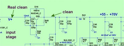
With a large PS decoupling bank , and simple cap multipliers (below).
Any rail garbage is nearly gone after C30/23. No matter what garbage
DIY PS I use , only < 2mV gets past Q20 (the multiplier).
Folded cascode current based input stages are unaffected , and a
>100db high NFB PSRR input stage is nearly immune.
Edit - you can also go "anal" and shield your trafo primary/secondaries....
OS
Attachments
Last edited:
It is in the current, Bonsai, so you need a current probe (or its equivalent) to see it easily.
Yes - I have a Tektronix current probe. At HF you also have electric field coupling as wel but I have rarely found this to be a problem in my layouts.
I used a pair of STAX h/p's for about 6 months when I lived in Tokyo along with the partnering tube amp - fabulous, relaxed sound.
They belonged to the lab at work . . . was a very good place for an audio nut like me. Two AP's, loads of Philips CD decks, amplifiers etc.
They belonged to the lab at work . . . was a very good place for an audio nut like me. Two AP's, loads of Philips CD decks, amplifiers etc.
There are three issues that I think are either not known about, misunderstood or just ignored that are important to the understanding of audio perceptions.
The first is the "Critical Band" model of human hearing. There are several ways of defining the critical bands. One is to use a filter on noise and widen it until the noise is no longer perceived as a sine wave. The other is to switch between two sine waves close in frequency and widen the gap until they are perceived as two different frequencies. A second tone in the same critical band as the first will cause "masking."
One take away from this is that to do perceptual testing the noise in each critical band should be below the limits of human hearing sensitivity.
Another issue with critical band masking is that if one tone is in one critical band and the second is in a different critical band close to the first then it is only masked if there is a 30 dB or so difference. (This is way oversimplified!)
This is often used to explain why second harmonic distortion is hard to perceive if it is more than 30 db (.1%) down.
Now the second issue is a bit better known, Fletcher Munson curves. Our sensitivity to frequency response is level dependent. A tone at 40 hertz 60 dB re 2 uPa is perceived as being as loud as a 3,000 hertz tone at -8 dB re 20 uPa. Yet the same 40 hertz tone at 80 dB re 20 uPa is perceived as being as loud as a 3,000 hertz tone at 60 dB re 20 uPa. A change of 48 dB in relative volume just from level shifts! That is why to get accurate tonal balance you must play music at the same volume at which it was recorded.
Now this also affects masking. So that listening at an average level of 60 dB re 20 uPa the low frequency energy of a 60 hertz tone would need to be about 47 dB louder than a 1,000 hertz tone to mask it. But the 20th harmonic would only need to be at the same level!
From power supply measurements the radiated field would only be down 15 db at that harmonic! So it can been seen that power supply noise can mask the midrange, if it is not carefully controlled.
Now the masking level required of low frequencies to mask higher frequency goes up quite dramatically at lower levels. This adds to the concept that listening tests with headphones at lower levels but with the outside noise blocked allows perception of higher order distortions better.
It also means that ABX perception tests need to not only control background noise level but also testing reproduction level.
The third biggie is that the energy spectrum of music has a loss of energy as the frequency increases. For testing we model this as pink noise that falls of as 3 dB per octave and has a 10 dB dynamic range.
That creates the issue of bit length limited recording. If I have a 16 bit recording of pink noise from 20 to 20,000 hertz and then drop the level by 60 dB (Lose the 10 least significant bits.) then any signals more than 26 dB below clipping will be lost. My calculator gives me 26 dB / 3 = 8.67 and 20 raised by 8.67 octaves is 4,160 hertz! Music as most here know is not pink noise, so rolls off even more. (Particularly if one allows 20 dB dynamic range.)
So in my perusal of Bill Waslo's test it does not matter that his hidden tracks have high frequencies at normal levels. When they are dropped by 60 dB virtually all of the high frequency content is lost. Now there is some advantage to low frequencies of the high level track masking the low level track high frequency ones, but as there is no energy in the critical bands around 2,000 - 6,000 hertz the quieter track is masked extremely well.
However this does not translate to the masking perception of distortion! Distortion has high frequency components. In addition if we use a perceptually perfect loudspeaker with .1% distortion, this also distorts the other distortion products and can then place them high enough in frequency that they are unmasked. That helps to explain why higher order distortion products are worse than simple second or third harmonis.
Bill Waslo certainly can do a spectrum of the high frequency that remains after dropping the 10 LSBs. My quick view did not find any significant frequencies to rise above the expected masking levels.
Last edited:
From power supply measurements the radiated field would only be down 15 db at that harmonic! So it can been seen that power supply noise can mask the midrange, if it is not carefully controlled.
Sorry I just don't see what you are getting at here.
JN
Attached is the TDR using the same technique as before. The data sheet does not give either value but if I measure it I'll PM you as this is intended to give me a market advantage.
Again, you provide very little information, leaving one guessing. I hate you for that.
That said, I understand your wish to control IP.
If your tdr is a step, the waveform is looking like an inductor. That would be consistent with common resistors and typical connections.
If your tdr is a pulse, you are seeing a clean resistor.
In either case, it looks like you've matched the generator impedance to prevent second reflections from the line/source mismatch.
The compromise is a lowering of the velocity of propagation as the Effective Dielectric Coefficient (EDC). I say EDC, as you've a twisted pair(s), which is not a fully constrained t-line. As such, the higher inductance is accommodated with the term Effective dielectric constant.
LC = 1034 EDC, L in nh/ft, C in pf/ft
Vc = 1/sqr(EDC)
Good luck with the cable. I hope the conductor insulation is robust enough for the task. Did you work out a hipot value for on spool and after installed to insure insulation integrity?
One good thing is, you can use the tdr as well, looking for overbends and insulation problems. Course, tdr will have limited length capability due to losses in insulation, proximity to tray rungs, conduits, and other cables.
John
ps. Another option is available as well...
If your tdr is a pulse, you are seeing a clean resistor.
In either case, it looks like you've matched the generator impedance to prevent second reflections from the line/source mismatch.
Good luck with the cable. I hope the conductor insulation is robust enough for the task. Did you work out a hipot value for on spool and after installed to insure insulation integrity?
One good thing is, you can use the tdr as well, looking for overbends and insulation problems. Course, tdr will have limited length capability due to losses in insulation, proximity to tray rungs, conduits, and other cables.
John
ps. Another option is available as well...
Pulse, CL3 rated (300V) and can use a much slower pulse for longer lengths, of course less accurate.
Shocked me to get so much right on a first pass.
Sorry I just don't see what you are getting at here.
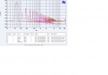
Attached is the noise just from a power transformer. It puts this out both as a voltage into the filter circuit that should clean it up AND as flux leakage that gets into everything from the chassis to any circuit loop.
Due to the Fletcher Munson effect you won't hear the line frequency, but the higher frequencies will mask desired signal.
Attachments
Last edited:
That creates the issue of bit length limited recording. If I have a 16 bit recording of pink noise from 20 to 20,000 hertz and then drop the level by 60 dB (Lose the 10 least significant bits.) then any signals more than 26 dB below clipping will be lost. My calculator gives me 26 dB / 3 = 8.67 and 20 raised by 8.67 octaves is 4,160 hertz! Music as most here know is not pink noise, so rolls off even more. (Particularly if one allows 20 dB dynamic range.)
Try 24bits no dropping LSB's use FP scaling and dither back to 24bits. Do I need to post a picture, at 24 bits a -40dB 4k tone can by dropped by 60dB and amplified again by 60dB and is fully recovered it is not lost?
Try 24bits no dropping LSB's use FP scaling and dither back to 24bits. Do I need to post a picture, at 24 bits a -40dB 4k tone can by dropped by 60dB and amplified again by 60dB and is fully recovered it is not lost?
Did you listen to the recovered hidden track? I suspect it was not recorded at 24 bits.
Or are you now arguing that digital music should always be recorded and distributed at 24 bits?
Or just another failure to communicate?
Attached is the noise just from a power transformer. It puts this out both as a voltage into the filter circuit that should clean it up AND as flux leakage that gets into everything from the chassis to any circuit loop.
Due to the Fletcher Munson effect you won't hear the line frequency, but the higher frequencies will mask desired signal.
So the hum is at full scale while you listen, your poor speakers. In this case let's say I measure the radiated SPL of the hum with no input what is it? Then I presume from your plot the 4k noise is -100dB below this. Now what is the typical SPL of the program content at 4k? Just asking for some numbers.
Did you listen to the recovered hidden track? I suspect it was not recorded at 24 bits.
Or are you now arguing that digital music should always be recorded and distributed at 24 bits?
Or just another failure to communicate?
No, I'm saying this test could be done on digital files as if it was mixed in with a pot in an analog sense. In any case even with 16bits the attenuation loses only when the signal is below the 1 LSB dither noise
Last edited:
So the hum is at full scale while you listen, your poor speakers. In this case let's say I measure the radiated SPL of the hum with no input what is it? Then I presume from your plot the 4k noise is -100dB below this. Now what is the typical SPL of the program content at 4k? Just asking for some numbers.
On a microphone preamp with 60 dB of gain this can be an issue if not acknowledged. Easy to fix. External power supply or internal with a subcase for the power supply.
Using the model of -3 dB / octave, the sensitivity on music is +15 dB. So the harmonics drop as expected, the hearing sensitivity increases by about the same amount and the signal drops by 15 dB.
I think that makes it clear that power supply issues may show up as a midrange issue before being obnoxious as hum.
No, I'm saying this test could be done on digital files as if it was mixed in with a pot in an analog sense. In any case even with 16bits the attenuation loses only when the signal is below the 1 LSB dither noise
No argument. The results of the test also follow the critical band human hearing model. Nothing surprising here. Nor is it surprising that high order harmonic distortion is perceptible especially when listening in a quiet environment at moderate levels.
I think that makes it clear that power supply issues may show up as a midrange issue before being obnoxious as hum.
I still can't work out if this is a fabricated edge case boogyman or you are just pointing out that a really ingenious idiot can make something this bad. Sorry for being thick, but if you are coupling 20th harmonic at -15dBFS you need your soldering iron taking away. (not you, people who can screw up this badly)
- Status
- Not open for further replies.
- Home
- Member Areas
- The Lounge
- John Curl's Blowtorch preamplifier part II