Funny idea to ask me to decompensate my probes and then to assume that the
risetime of an AF amp should change like that, only with some second order effect.
And I cannot decompensate my probes, they have an amplifier directly at the tip.
Biggest thing since sliced bread, those probes, btw. 0.6pF load.
risetime of an AF amp should change like that, only with some second order effect.
And I cannot decompensate my probes, they have an amplifier directly at the tip.
Biggest thing since sliced bread, those probes, btw. 0.6pF load.
Last edited:
Patenting that is disgraceful, but I suppose I shouldn't be surprised.I've occasionally pointed out that driven guard layout can nearly eliminate PCB dielectric concerns at audio for the few nodes high enough Z to matter
in fact someone got a patent on driven guard PCB traces "for audio amplifier"
In one design of a tube preamp for an audiophile I got a pushback when I suggested a couple of locations for teflon standoffs. It was curious, because the same guy worries about other presumably tiny effects. In this case, to minimize loading of certain anodes I used a fairly high impedance network to minimize distortion.
Normally I use as low of an impedance as possible, within the constraints of the ability of the circuit to drive them.
As risk of opening another can... Other than mixed signal work is there ever a justification in audio for 4 layer boards assuming a significant level of competency with layout?
Maybe not, but the cost difference is only a few % these days - even for prototypes - so you might as well allow yourself the luxury...
Edit -- But then my first builds - both valves and solid state - used good old tagstrips! Now that's real multilayer!
Last edited:
You don't appreciate USDA Prime Grade voodoo.
LOL... What's the MIL spec for that?

The Tek article on hook was indicative of effects that reached down into the audio band, if I recall correctly.
At what node impedances? I've used PTFE standoffs for ESL and condenser mike polarization, but can't think of anywhere else in an audio application that they were necessary (at the cost of significantly poorer mechanicals than epoxy-fiberglass).
Load of rubbish,
rsavas wrote
“if you can't lay out your own pcbs”
not
“if you don’t lay out your own pcbs”
However, everybody seems to ignore the real reason we used Teflon for circuit board material: CIRCUIT HOOK
A term used by Tektronix denoting a problem that they had with their attenuators, etc using normal fiberglass board material. This was described in an article in an engineering design magazine about 40 years ago. It is related to DIELECTRIC ABSORPTION and the Dielectric Constant which can be very high value in cheap board material
It might have been a problem in instruments for measuring pA (or fA on clean boards)
What is the Z of the audio circuits?
George
Attachments
We just have to find that article, as I recall the Tek folks were appalled (and it took them a while to identify the cause). Tek was using patches of copper as a convenient way to realize rather small capacitors for high frequency compensation in the vicinity of some early high-frequency ICs in the vertical amplifier signal chain.At what node impedances? I've used PTFE standoffs for ESL and condenser mike polarization, but can't think of anywhere else in an audio application that they were necessary (at the cost of significantly poorer mechanicals than epoxy-fiberglass).
For the one preamp I mentioned which never saw the final light of day as far as production, the resistance in one location was about a megohm. There were at most two nodes where I thought it would be prudent to use a standoff. And there was no way to implement a guard ring, which is otherwise a good practice for very high impedances and small dimensions.
EDIT: and I should add this was mostly a point-to-point wired device.
Last edited:
The one remark I have about doing one's own board layout is that you become the pacing item now for practically everything, and as someone said you probably don't get much sleep.rsavas wrote
“if you can't lay out your own pcbs”
not
“if you don’t lay out your own pcbs”
George
But this must be balanced with the advantage of being able to get exactly what you want, or think you want, or at least as close as you can manage.
I worked with a guy who was the best layout person to date in my experience. The product was a switchmode amp based initially on an IR reference design, and using the DirectFETs and an earlier version of an integrated IR driver. He also serviced analog electronic music synthesizers on the side. He digested the IR literature with recommendations for layout for best performance, and applied them with great skill. If he weren't being kept busy with other work I'd be trying to use him going forward.
I have a Brüel & Kjaer Psophometer 2429 here that has all input circuitry, including attenuators, on Teflon PCB. 20Hz to 20kHz (!) Please tell me that engineers at B&K were dumb.
Brüel&Kjaer 2429
Brüel&Kjaer 2429
Also as mentioned teflon is triboelectric. ADI had an ancient Analog Dialogue iirc that warned about minute currents flowing for substantial time if a teflon standoff were mechanically stressed. I believe that, similar to some extent to PCB material "hook", that these issues got better with better processing.
I got an email letter today about microwave components fabricated on glass substrates, oddly enough.Stupid question;
Has actual glass ever been used as a substrate?
Just curious.
A series-feedback network I'm using for a pretty-good MC stepup stage with three paralleled JFETs run at fairly high currents has a 3 ohm R to common and a 57.6 ohm as the feedback resistor. The contribution from the thermal noise of the 3 ohm is small but not completely negligible.The highest node impedance in any of my circuits is about 2.5k (parallel combos of resistors). A good way to minimize parasitic capacitance problems
One could ask why feedback at all, and the main reason is to make the gain adjustment-free, with secondary enhancement of distortion performance and overload margins. There is also a d.c. servo, but an unusual one.
I can't find the Tek article either but this oldie but goodie does mention it at the end of the section on dielectric absorption.
http://www.analog.com/library/analogDialogue/archives/43-09/EDch 12 pc issues.pdf
But I mean, who would use precision analog techniques in a high end audio device when a something shiny will do instead?
http://www.analog.com/library/analogDialogue/archives/43-09/EDch 12 pc issues.pdf
But I mean, who would use precision analog techniques in a high end audio device when a something shiny will do instead?
That's got to be the article: W. Doeling, W. Mark, T. Tadewald, and P. Reichenbacher, "Getting Rid of Hook: The Hidden PC-Board Capacitance,"I can't find the Tek article either but this oldie but goodie does mention it at the end of the section on dielectric absorption.
http://www.analog.com/library/analogDialogue/archives/43-09/EDch 12 pc issues.pdf
Electronics, October 12, 1978, p 111-117.
Note that ADI describes it as a capacitance variation with frequency and most important below 10kHz:
"PCB 'hook,' similar if not identical to DA, is characterized by variation in effective circuit-board capacitance with frequency (see Reference 1). In general, it affects high impedance circuit transient response where board capacitance is an appreciable portion of the total in the circuit. Circuits operating at frequencies below 10 kHz are the most susceptible. As in circuit board DA, the board's chemical makeup very much influences its effects."
I will be ordering some PC cards next week. Simple 2 layer FR4. So what test card should I use to measure how much the PC material really affects an audio signal? Should I lay out a winding long trace over a ground plane and drive it with a modest 10,000 ohm source and a high impedance 10 M load. Test this with square waves from say 20 -20,000 hertz?
Should I do an FET buffer with and without an input guard ring?
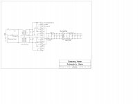
On an entirely different subject I have decided to simplify my power supply work to some simple projects. Attached is a schematic with values of a basic low noise DC power supply. The ripple should be .04 volts at 120 hertz and virtually no other AC power line noise that I can measure.
(This is part of the PC order.)
Should I do an FET buffer with and without an input guard ring?
On an entirely different subject I have decided to simplify my power supply work to some simple projects. Attached is a schematic with values of a basic low noise DC power supply. The ripple should be .04 volts at 120 hertz and virtually no other AC power line noise that I can measure.
(This is part of the PC order.)
Attachments
- Status
- Not open for further replies.
- Home
- Member Areas
- The Lounge
- John Curl's Blowtorch preamplifier part II