When running single BTL the effective output voltage doubles
No, it doesn't.
Back EMF increases impedance!
The voice coil inductance can induce phase shifts as well as the system mass so worst case it lowers it. I will see if I can find a curve where it dips below the DC resistance. I used to have a classic case but I think it got lost in a computer crash.
The other example data I used to keep with that was the one that showed the acoustic center was not at the voice coil. Won a few bets with the pair.
But the drivers I play with are all high efficiency types.
One of the nifty differences is that transducers for efficiency should not have flat frequency response. For a given cone size as you move it the same distance but more often the output should rise.
Last edited:
@SY
What is a power cube? I am not familiar with the term and(or the device. Please explain.
The Horse's mouth:
audiograph | Home of the PowerCube
What Audio Precision says about it:
AP High Performance Audio Analyzer & Audio Test Instruments : Service & Support
"one that showed the acoustic center was not at the voice coil"
I would think that both the gap to voicecoil length and the former length would move the apparent acoustic center and the thinking that lining up the voicecoils in a vertical line for time alignment is a very flawed assumption.
I would think that both the gap to voicecoil length and the former length would move the apparent acoustic center and the thinking that lining up the voicecoils in a vertical line for time alignment is a very flawed assumption.
"one that showed the acoustic center was not at the voice coil"
I would think that both the gap to voicecoil length and the former length would move the apparent acoustic center and the thinking that lining up the voicecoils in a vertical line for time alignment is a very flawed assumption.
The velocity of propagation is faster through the cone than through air. So for a paper cone transducer it is where the area of the cone forward of the center is the same as behind.
Since efficiency is near max at max power ---- all you need to do is look at the rear panel power consumption (max) label. Or labeled Amps given at max. And calculate the actual total power output.
Trouble is that both US UL standards and most international standards for power drain that are put on nameplates are not based on continuous sine wave power output just below clipping.
The fallacy of the idea above is shown in both power ratings and nameplate current draw specs that show up all over the web. Nameplate current drain shows up on spec sheets and is generally far less than what you would expect from rated full power.
This is actually reasonable because continuous wave power is irrelevant to any typical home and professional audio power amp operation involving music, speech or sound EFX.
Any real world audio signal that you want to listen to is not a pure sine wave, but is rather a multitone. That means that its peak-to-average ratio is >> 1, typically about 8 dB in the worst case and easily up to 20 in many real world applications.
labelling of Max power consumed is required by UL and other safety agencies. The amplifier max output Power cant be greater than what is drawn from the wall. useful for a reality check on mfr's claimed power output of amps...... and to size power needs/loading of the ac utility source.
-RNM
While its true that the UL requires related information to be on the nameplate, it is not based on anything like full power operation. I forget what the standard is exactly, but memory suggests that it is less than 1/3 power.
Therefore using it is suggested, as some kind of "reality check" is not at all relevant.
Thanks.labelling of Max power consumed is required by UL and other safety agencies. The amplifier max output Power cant be greater than what is drawn from the wall. useful for a reality check on mfr's claimed power output of amps...... and to size power needs/loading of the ac utility source.
-RNM
Below is Crown's take on duty cycle of different signal types.

Dan.
No, it doesn't.
I'm confused, isn't Max just talking about bridged amps on +-50V rails, all else being equal, can deliver 200V p-p?
theoretical.
All I was referring to, I've had confused folks at seminars claim is is not theoretically possible (subject was xDSL drivers).
The voice coil inductance can induce phase shifts as well as the system mass so worst case it lowers it. I will see if I can find a curve where it dips below the DC resistance. I used to have a classic case but I think it got lost in a computer crash.
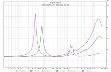
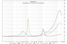
I have yet to find a driver motor unit that is itself a difficult Z load.
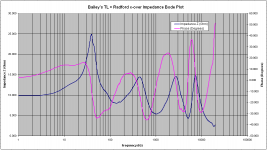
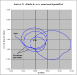
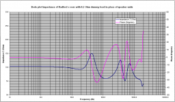
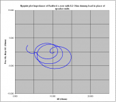
In all cases, the low Z values I’ve measured across the terminals of a speaker box are to be attributed to the passive cross over used.
I give you an example
George
Attachments
-
 1 Bode Plot whole speaker.PNG57.4 KB · Views: 197
 -
 2 Nyquist Plot whole speaker.PNG23.7 KB · Views: 198
 -
 3 impedance of drivers on air.jpg100.8 KB · Views: 206
 -
 4 impedance of drivers on enclosure.jpg105.9 KB · Views: 200
 -
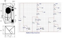 5 Bailey's TL + Radford FN 8A 3 Way Cross-Over.JPG140.3 KB · Views: 200
 -
 6 Bode plot of x-over with dummy loads.PNG50.5 KB · Views: 81
 -
 7 Nyquist plot of x-over with dummy loads.PNG21.2 KB · Views: 72
I have yet to find a driver motor unit that is itself a difficult Z load.
In all cases, the low Z values I’ve measured across the terminals of a speaker box are to be attributed to the passive cross over used.
I give you an example
George
George, I do belive difficult loads require actual XOs and drivers to turn from reasonable to difficult. Look at the plots you procvided - the one depicting only the XO network is easier than the one of the XO network with connected drivers. That one shows a phase shift of +/- 40 degrees, which is not easy but is still far from deadly
If memory serves (it's been some time from 1977), a friend working on his degree measured a Yamaha NS-1000 monitor with a phase shift of + 35, -70 degrees, the minimum being very near an impedance drop to some 3 Ohms or so, somewhere 250-350 Hz. At a nominal output voltage of 40 p-p (or if you prefer at 20dBW) the output stage was being asked to deliver around 16 Amps of current. Very, very few amps were capable of that in those days. So on most amps, the speaker's bass lines sounded thin and insubstantial. Even in case of Yamaha, only their top of the line 2010 integrated amp could cope with that, and it did cost a pretty penny. And there's a hell iof a lot going on at 250-350 Hz, which is in fact already the midrange, so losses are easily heard.
This is a classic problem of amplifier design. For a given system a max instantaneous power of 100W may be needed. But if you specify an amplifier for 100W continuous you may be using much larger, more expensive transformers and heatsinks than you actually need.
This is not a problem of electronics but a problem of economics. If you are going for a maximum fidelity amp, you will want those 100W deliverd in style right up to its specs. If it's an economy class device, you will be overdoing it, very likely.
There's a reason why people put 1,000 VA power transformers in nominally 2*100W amps. That amp could be designed as an ideal voltage source, so it might be asked to deliver 100/200/400 W into 8/4/2 Ohms, and that juice has to come from somewhere, right?
There's a reason why people put 1,000 VA power transformers in nominally 2*100W amps.
Several reasons:
Ignorance of what is actually required for excellent sound.
Bragging rights.
That amp could be designed as an ideal voltage source,
Actually pretty hard to do, due to the fact that all the parts have finite losses.
so it might be asked to deliver 100/200/400 W into 8/4/2 Ohms, and that juice has to come from somewhere, right?
If you had a perfect constant voltage power supply, the above would still be impossible.
The most common way to obtain 100/200/400 W into 8/4/2 Ohms is to underrate the amp at the higher impedance settings. Very commonly done.
I think the point dBV is making is that if you want an amp that can handle a difficult load, you need a decent power supply.
A decent amp is for practical,purposes a voltage source. A few milli- Ohms output Z variation over the audio band is not what will cause problems. Power supplies that crap out at 4 ohms will.
A decent amp is for practical,purposes a voltage source. A few milli- Ohms output Z variation over the audio band is not what will cause problems. Power supplies that crap out at 4 ohms will.
I have yet to find a driver motor unit that is itself a difficult Z load.
In all cases, the low Z values I’ve measured across the terminals of a speaker box are to be attributed to the passive cross over used.
I give you an example
George
George,
As I read your measurements at 20,000 Hz the HF drops to 2.5 ohms. There is shown in the schematic 2.4 ohms in series with the tweeter. Does it really behave as a .1 ohm load? What is the DC resistance?
Last edited:
George,
As I read your measurements at 20,000 Hz the HF drops to 2.5 ohms.
C3 is also resonating with L4 which is responsible for the bump. The resistors are optional and are switched out for EQ, so worst case would be to simulate without them.
Last edited:
Originally Posted by Max Headroom
When running single BTL the effective output voltage doubles
Brain fart Jacco ?.No, it doesn't.
Correct.I'm confused, isn't Max just talking about bridged amps on +-50V rails, all else being equal, can deliver 200V p-p?
Dan.
- Status
- Not open for further replies.
- Home
- Member Areas
- The Lounge
- John Curl's Blowtorch preamplifier part II