I'm surprised he didn't come up with a copyrighted name for it!That was also a Carver thing, inverting one channel. Later this was discontinued. I guess the mag coil drive was improved to a point where it was no longer needed.
-Chris
Yes, it's something that has occurred to many. Philips at one point even began to show it in app notes, but it began long before that.
AudioXpress and Linear Audio will do a combined project on an SMPS specifically designed for audio.
Jan
Great! When can we expect it?
I showed how to dramatically (in some cases) shrink FIR's in my LA article. A dishwasher does my dishes, quietly if not quietly enough for you.
Jan or Scott could one of you tell me what issue of LA this article was in, I would like to get a copy of it so I can read that.
Jan that will be great to read about using a smps that is audio specific and not just go to Hypex who isn't interested in OEM sales. What is needed for that and how you size a smps power supply to match a class-d amplifier would be very informative.
I just downloaded PCB123 from Sunstone and was trying to find how to download the Analog devices library but couldn't find the ADAU1701 in the list they showed. Is there an easy way to get these libraries of parts besides their website? Anyone use this tool?
Last edited:
Jan or Scott could one of you tell me what issue of LA this article was in
Let me find that for you using the internet search engine DuckDuckGo. Presto, here it is.
AudioXpress and Linear Audio will do a combined project on an SMPS specifically designed for audio.
Jan, you're the Man.
(drivers, please press ignore me now)
Hi Brad,
That is the one thing that drove me nuts about Carver Corp. But I do have to tip my hat to Bob Carver for some ingenious circuits he came up with with the high reliability his designs normally have. Vic Richardson did a fair amount of excellent design work as well for Carver Corp.
-Chris
Me too!I'm surprised he didn't come up with a copyrighted name for it!
That is the one thing that drove me nuts about Carver Corp. But I do have to tip my hat to Bob Carver for some ingenious circuits he came up with with the high reliability his designs normally have. Vic Richardson did a fair amount of excellent design work as well for Carver Corp.
-Chris
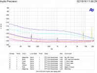
Well I just completed my second low noise amplifier and used it to test a theory about Power Supply Rejection Ratios.
First I just used the data sheet circuit with 10 uF bypass capacitors at each chip and on each rail. The I added 25 Farad super capacitors to each rail.
The before curve matched the data sheet curve with a 1/F corner at 1,000 Hertz.
Adding the super capacitors instantly raised the noise as shown.
Letting it age under power the noise dropped. By the end of the afternoon the noise had dropped below that of the data sheet bypass suggestions. The next day the noise floor was even lower. Input shorted.
My conclusions:
The super capacitors I used do indeed need to reform after storage or simply put, there really is a burn in effect.
PSRR is a two way street. A low impedance low noise power supply will reduce noise in the circuit connected to it.
Unknown is if PSRR is symmetric as to reducing noise in and out.
So using power and ground planes with excess capacitance will actually reduce circuit noise.
Attachments
Last edited:
It took some looking to find what article was referenced to Scott where there was a discussion of dsp and filters. It appears this article is mainly directed towards RIAA compensation in the digital domain. How much information in this article is aim at FIR filter optimization, is this just a simple generalization of using FIR filters on a minidsp?
So using power and ground planes with excess capacitance will actually reduce circuit noise.
What if the circuit has infinite PSRR? If you hook up a 797 like on the data sheet it has .9nV noise down to 10Hz or so nothing will make it lower other than cooling it.
What if the circuit has infinite PSRR? If you hook up a 797 like on the data sheet it has .9nV noise down to 10Hz or so nothing will make it lower other than cooling it.
The chip I used is specified as 76 dB PSRR at 1,000 Hertz gain of 5 Delta VCC +/- 100 mV.
I look at the image and it seems like the corner frequency has moved, although it could just be too far below the residual noise.
Now we can talk about the PSRR test circuit. Since adding capacitors to the device under test would ruin the standard test circuit, it does raise the question about how the test really reflects actual in circuit use.
The the real question is have you tried it? The data sheet shows only 4.7 uF in parallel with .1 uF. It does not address ground planes and mega capacitance. The assumption is that the noise should not go down, but if you model the circuitry as a simple resistor of say 50 ohms, the noise should go down if that resistor is paralleled by a resistor of 1 ohm. Is the assumption that PSRR symmetric valid?
It took some looking to find what article was referenced to Scott where there was a discussion of dsp and filters. It appears this article is mainly directed towards RIAA compensation in the digital domain. How much information in this article is aim at FIR filter optimization, is this just a simple generalization of using FIR filters on a minidsp?
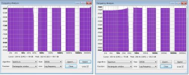
One simple trick that works for a lot of FIR filters with low frequency poles or zeros. It amounts to a phase rotation equivalent to a fractional sample delay which works in some cases better than windowing. Picture below shows Audacity's built in FIR RIAA right and mine left. The input in both cases was a spectrum with "holes" inverse RIAA'd essentially a multi-tone using every bin.
The FIR on the left is shorter and minimum phase (which you can't see here) there is low frequency ripple from the windowing visible on the right FIR. The miniDSP does not do FIR's you will probably find the throughput at 50MIPs on that processor will not do much FIRing, the miniSHARK is a better bet.
Attachments
Last edited:
Is the assumption that PSRR symmetric valid?
No, certainly not vs. frequency since the comp cap is usually tied to one of the rails.
Your resistor analogy is lost on me, the circuit is an amplifier with an equivalent input noise of 50 Ohms. Nothing on the supply can make that go away.
Scott,
thank you as always. I am seriously looking to use the ADAU1701 chip as that looks to do so much of what I am wanting to do with a few external chips to add some other functionality. I downloaded the PCB123 software from Sunstone last night but the library they had for AD didn't have that chip listed. I am looking for how I get that library so I can import that into the PCB software. I'm still a bit unsure on what class-D chip or pair of chips to use to have the low distortion output at elevated levels but many say that shouldn't be a real problem. I'm just not sure how you parallel two of those chips to have the clean power that I desire. I'm trying to understand exactly what people are meaning when they say to parallel two of those chips. I know you can do a bridged configuration but I would like to run a parallel or push pull configuration if that really is possible.
thank you as always. I am seriously looking to use the ADAU1701 chip as that looks to do so much of what I am wanting to do with a few external chips to add some other functionality. I downloaded the PCB123 software from Sunstone last night but the library they had for AD didn't have that chip listed. I am looking for how I get that library so I can import that into the PCB software. I'm still a bit unsure on what class-D chip or pair of chips to use to have the low distortion output at elevated levels but many say that shouldn't be a real problem. I'm just not sure how you parallel two of those chips to have the clean power that I desire. I'm trying to understand exactly what people are meaning when they say to parallel two of those chips. I know you can do a bridged configuration but I would like to run a parallel or push pull configuration if that really is possible.
No, certainly not vs. frequency since the comp cap is usually tied to one of the rails.
Your resistor analogy is lost on me, the circuit is an amplifier with an equivalent input noise of 50 Ohms. Nothing on the supply can make that go away.
Not symmetric to the rails but in vs. out.
And I have two cards where the power supply does change the noise level.
And I have two cards where the power supply does change the noise level.
Well figure out what's really going on, certainly before you publish anything. How do you think all the graphs on data sheets are made? How did those NIST guys measure -200dBV on batteries?
Well figure out what's really going on, certainly before you publish anything. How do you think all the graphs on data sheets are made? How did those NIST guys measure -200dBV on batteries?
I have built a test circuit for the standard PSRR tests. Have played with it a bit. Now the NIST guys made it clear how they made measurements with a bit of effort.
My observation was simple, lowering the power source impedance reduces the noise of the circuit under power.
My suggestion is simple, if using an AD797 circuit, place a whopping big pair of capacitors across the rails and see if the noise goes down. Now I'll try on rail at a time to see if the path is through the compensation capacitor.
My suggestion is simple, if using an AD797 circuit, place a whopping big pair of capacitors across the rails and see if the noise goes down.
It doesn't, it can't, it's already at the thermal noise limit of the input devices, no different than off of battery supplies. Really Ed your being too silly today.
If I short the output the noise goes away.

Can you confirm that the supercapacitor noise stays away if the circuit is not left on? IE it's a one time thing?
It should creep back up when not in use and then go back down in use. But figure this was around a year of not in use.
- Status
- Not open for further replies.
- Home
- Member Areas
- The Lounge
- John Curl's Blowtorch preamplifier part II