The oldie of maximum power transfer occurs when source impedance matches the load. Now this doesn't work for most sources but in this case is relevant.
Optimum power generation occurs when the magnetic losses equal the resistive loses.
Ed
This is a bit (much) more complicated .
I would suggest a classic reference:
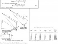
Modern Power Station Practice
Volume 7, Chapters 2 and 5
http://www.amazon.com/Modern-Power-Station-Practice-v/dp/008016062X/ref=sr_1_17?s=books&ie=UTF8&qid=1447614852&sr=1-17
Ever consider what would happen to a nuke plant if the source actually matched the load?
Every power plant, regardless of the energy generation method, during commission undergoes a full run across the entire load-bandwidth (against performance diagrams and all) .
Especially for nuke plants, have you thought of how many control steps are involved btn the nuke core and the electrical generator?
George
George
I was pointing out that if a power plant source matched the load half of the energy would be dissipated in the source. Very much so not a good thing! In the case of energy harvesting the power levels are so low that maximum energy transfer can be done. But of course the mechanical impedance of the source comes into play.
I was pointing out that if a power plant source matched the load half of the energy would be dissipated in the source. Very much so not a good thing! In the case of energy harvesting the power levels are so low that maximum energy transfer can be done. But of course the mechanical impedance of the source comes into play.
I have always thought that the best way to view this is that:
If the source impedance is a value > 0, then max power transfer occurs when RL = RS. Hence matching a tube anode impedance to a speaker's using a transformer of the correct turns ratio.
Many of us oldies grew up with this!
It is also true, I suppose, when Rs=RL =0, but only for a non-useful infinitely short period of time!
With most SS amps having Rs -> 0, it is not useful to talk about maximum power transfer in this way.
Hi Scott, perhaps you are not sure of what to listen for.That would be hard since I don't hear these things. I can clamp a cheap RFI damping ferrite over any of the cables in my system and I don't hear anything, so according to some I'm deaf or a liar.
John will now intercede and point out that I don't have any gear that could possibly resolve at his level.
I just tried a clamp on cheap RFI damping ferrite on the speaker leads of my small but quite good Panasonic shelf system (breakfast AM radio).
Result is a subtle set of effects.....on first listen bigger perceived instantaneous dynamics and the overall sound is as if it is shifted up a micro/semitone, but on more extended listening a general unease and 'wrongness' in the sound with a distortion cast and displeasing unnatural dynamic behaviour, notably on spoken vocal content.
You might need repeated A/B comparisons to 'get' the differences.
Dan.
Without a rf field measurement for your home the effectiveness of a RFI damper is truly un-know . And the effect on your system . Once in Cincinnati under the University of Cincinnati fm 50kw antenna in it shadow the rf was very low 2 block over it was 3 volts . Well that what we measured . So for me first a rf backround measurement then see what effect the ferrite may have.That would be hard since I don't hear these things. I can clamp a cheap RFI damping ferrite over any of the cables in my system and I don't hear anything, so according to some I'm deaf or a liar.
John will now intercede and point out that I don't have any gear that could possibly resolve at his level.
Where I am now in Georgia with a metal roof We go out side to use the cellphone my backround rf is rather low in side . The cellphone tower is in sight of my home. Well that is my experience so far. Regards.

Or, more likely, there's nothing real to hear......Hi Scott, perhaps you are not sure of what to listen for.

But most of the protaganists on this thread are well capable of measuring incidental rf effects, and let's face it they are rare, especially 50kW local transmitters.....Without a rf field measurement for your home the effectiveness of a RFI damper is truly un-know .
I was pointing out that if a power plant source matched the load half of the energy would be dissipated in the source. Very much so not a good thing
Ed
In power AC generators, it is the rotor slip that (self)regulates this game to a large extend.
The load reactance is to be balanced through the internal inductances of the generator, mainly the synchronous reactance, which is the consequence of rotor slip.
Look at the formula lower case greek delta (δ) is the rotor angle (or angle btn max magnetic flux and max emf generated) , lower case greek theta (θ) is the load impedance angle. Max power output is when the two angles become equal.
The max (I^2)*R losses within power generators are minimal (btn 0.1% and 0.2% of Pmax)
That was an issue Edison got wrong and Tesla got right.
Tesla worked on AC, he had to take the various inductances of the generator into account from the start (plus, he was a genius)
the power levels are so low that maximum energy transfer can be done. But of course the mechanical impedance of the source comes into play.
Interesting (applicable to phono cartridges?)
George
Attachments
Last edited:
But most of the protaganists on this thread are well capable of measuring incidental rf effects, and let's face it they are rare, especially 50kW local transmitters.....
If we are to communicate in a meaningful way on this, we all would have to use the same pick-up antenna(s) and utilize the same RF measuring procedures.
George
For some reason, a cell phone doesn't work at all in my auditing room.
If I open the door and take two steps into the 2nd floor hall, everything's fine.
I recall it started after the room was sound-proofed on all surfaces with rockwool and/or Hawaphon panels.
If only I could do a rf field measurement.
If I open the door and take two steps into the 2nd floor hall, everything's fine.
I recall it started after the room was sound-proofed on all surfaces with rockwool and/or Hawaphon panels.
If only I could do a rf field measurement.
Hi Scott, perhaps you are not sure of what to listen for.
I just tried a clamp on cheap RFI damping ferrite on the speaker leads of my small but quite good Panasonic shelf system (breakfast AM radio).
Result is a subtle set of effects.....on first listen bigger perceived instantaneous dynamics and the overall sound is as if it is shifted up a micro/semitone, but on more extended listening a general unease and 'wrongness' in the sound with a distortion cast and displeasing unnatural dynamic behaviour, notably on spoken vocal content.
You might need repeated A/B comparisons to 'get' the differences.
Dan.
Are you trolling here?
This is the same bs promulgated by the sandman.
Hi George, I prefer to think that any relevant artefacts arising should be observable within the audio equipment itself. Say as common mode or diff mode PSU noise, or as simple input noise, etc etc etc. I don't think it's possible to standardise on a measurement, not least because even when external rf is present in extremis there is not necessarily even anything observable or audible.........If we are to communicate in a meaningful way on this, we all would have to use the same pick-up antenna(s) and utilize the same RF measuring procedures.
George
Andrew, you know me better than that.Are you trolling here?
So two people are saying the same ?.This is the same bs promulgated by the sandman.
Could you provide links please.
Dan.
Last edited:
Lucky, you do not seem believe in hearing any subtle differences. What is the problem?
The major problem is that he didn't say that. Could you perhaps address what people actually say rather than stuff you make up?
If only I could do a rf field measurement.
Jacco
For an informative area survey (not absolute measurement), you can start with a modulation envelope peak detector
Plug suitable wire lengths at the input (skip the series capacitor) http://www.diyaudio.com/forums/equipment-tools/264871-oscillation-sniffer.html#post4122213
Hi George, I prefer to think that any relevant artefacts arising should be observable within the audio equipment itself. Say as common mode or diff mode PSU noise, or as simple input noise, etc etc etc.
Lucky
This is correct for severe cases (either strong interfering field, or very vulnerable ‘victim’ system or both)
I don't think it's possible to standardise on a measurement
It is, that is if we are serious enough
e.g. see MIL-STD-416
http://snebulos.mit.edu/projects/reference/MIL-STD/MIL-STD-461E.pdf
not least because even when external rf is present in extremis there is not necessarily even anything observable or audible.........
If you have achieved such levels of immunity (even as a matter of favorable coincidences) good, but this is not a strong basis for generalizing
Radio Frequency Interference: How to Identify It and Cure It: The American Radio and Relay League Inc: Amazon.com: Books
http://rsgb.org/main/files/2012/11/EMC04-Final.pdf
Identifying Sources of Radio Frequency Interference Around the Home
How to: Assess RF Interference with a Spectrum Analyzer
EMI - RFI page
George
Attachments

Last edited:
First sentence is true. The trouble starts at the "hence". It is rare in audio engineering to have a matching impedance in this sense. Much more likely to have an appropriate impedance: usually a serious mismatch, but often called a "match". This confuses a lot of people!cliffforest said:If the source impedance is a value > 0, then max power transfer occurs when RL = RS. Hence matching a tube anode impedance to a speaker's using a transformer of the correct turns ratio.
Consider a pentode output stage. The impedance presented to the anode is much smaller than the anode impedance - maybe 5k versus 100k? A triode output stage might go the other way. The issue is not maximum power transfer, but best compromise between gain, power and distortion.
However, let us suppose we really were just interested in maximum power transfer. Then we would hit another problem: the pentode model of a current source in parallel with a high resistance has a hidden limit, namely the supply rail voltage. We can increase our output by increasing the impedance of the load but there is a limit which the maximum power transfer theorem ignores.
All electronics newbies are taught the theorem. Most quickly find that they never use it again, unless they work in RF, and so forget it. Some will drag it in to irrelevant situations and confuse themselves.
Why Mr. Marsh Sir, a blotterhead, you ?
The more intelligent a person is, the general note is that they have a tendency toward the more expansive chemicals. Joy and happiness in exploration and growth. Open to new things, Open to new science. An inherent capacity to change. Comfortable enough in their own skin to handle it.
The more negative of a ground pounder the person is, the general note is they have a tendency toward alcohol. Joy and happiness in downturn into established limits. Life in comfort behind a spear guarded fence. Not open to new things, living via negative proofing. Which is the horror of the religious doctrine and dogma that has taken over science.
The first is capable of seeing the nature of this deep problem.
The second is not.
Thus, the crux of the matter in the heart of most arguments here on the forum, and in other places.
Blind sides (seeking and maintaining the comfort of method and limits as a core mental emergence from instinct) of such nature ----are also open to manipulation.
For some reason, a cell phone doesn't work at all in my auditing room.
If I open the door and take two steps into the 2nd floor hall, everything's fine.
I recall it started after the room was sound-proofed on all surfaces with rockwool and/or Hawaphon panels.
If only I could do a rf field measurement.
The steel seems to have created a low level floating field or interference pattern. Micro reflections, rf diffraction/reflection/scatter, possibly.
I suspect that the issue is not RF field but a lack of the minimal functional coherence in the extant fields. This, in concert with a reduced I/O of fields to/from (passthrough) the room. A scatter filter in level and phase.
If the rockwool is floating and is fairly strong in dielectric considerations, low level capacitance (field storage) can do nearly the same trick but differently sourced, with regard to actual 'blocking' of cell phones. My guess is that your signal level near the door of the room will be higher on damp days, simply due to the rockwool components. Depends on their proximity to the door.
Last edited:
- Status
- Not open for further replies.
- Home
- Member Areas
- The Lounge
- John Curl's Blowtorch preamplifier part II