Billshurv,
No more rape seed oil in the States, they had to rename it Canola oil so as not to offend!
Pardon my lateness, i'm catching up, but:
The town of Sexsmith, Alberta where they grow a lot of Canola (the "Can" comes from "Canada") used to advertise itself as "The Rape Capital of Canada."
I am Danish, so I know what 88 means. Had two friends who was sent to 'camps' and survived - they have passed away now.
I'm in awe of your longevity.
nezblu,
That doesn't exactly market very well now does it! I never realized that is where the Can part of Canola came from. Just thought someone made up a new name for marketing purposes. Now I only use Canola or Olive oil in cooking, no more corn oil in my house.
They did make up a new name for marketing purposes. The rapeseed plant is related to mustard, and its oil is very bitter tasting. This is due to high levels of erucic acid, which damages your heart muscles in addition to tasting bad. (Likely not a coincidence.) To make canola oil, they used hybrid techniques to lower the acid levels of the rapeseed plant. "Can-O- LA" is an shortened version of "Canadian-Oil-LowAcid". Since then Monsanto has genetically modified it to make it resistant to its deadly herbicides, and most canola oil today is a GMO.
It is marketed as a "healthy" oil and many fall for the marketing hype. It actually is one of the worst oils for your health. Here's why:
1) Most vegetable oils in general are not good for your health. If you dig into the history of this you will find that all of the nonsense we've been fed for decades about the "badness" of fats and oils was actually created by the sugar industry. Sugar (especially high-fructose corn syrup) not only causes diabetes, but cancer, heart disease and a litany of other massive health problems. The sugar industry deflected the blame to fats, and everybody in the US was told to eat a low-fat diet.
2) Even if canola oil were "pure", it would not be a "healthy" oil. One of the early steps in processing canola oil is to remove the residual bitterness that couldn't be eliminated through the hybridization of the rapeseed plants. This is done by rinsing the canola oil with hexane. Hexane is a petrochemical that is one of the major constituents of gasoline. Canola oil is not tested for residual hexane content.
3) Even after rinsing with hexane, the canola oil is dark and greenish colored. To make it "look" healthier, they bleach it with sodium hydroxide (lye). The resulting oil is a light yellow, more like other common vegetable oils such as corn, sunflower, and safflower.
There you have it -- an oil created by mega-corporations and successfully marketed as "healthy", despite the fact that it is a GMO, the plants are treated with pesticides with long term effects likely worse than DDT, most vegetable oils (including rapeseed) are not good for your health, and that it uses vast amounts of chemicals in its production and those chemicals likely are found in the end product.
Olive oil is less bad for you than most vegetable oils, as long as you don't cook with it. (Heating it modifies its molecular structure.) Unlike what we've been told for the last many decades, animal fats such as lard and butter are (in general) better for your health than vegetable fats.
Back to amplifiers...
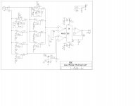
I am trying to finish up my article on power supplies and one open item is a method to measure the noise of some of the better power supplies. This is a circuit I think will work as a front end. Comments?
Hi Ed,
I requisitioned a Stanford Research lock in amplifier and put it in my office, so please repeat that noise measurement that you want to verify.
longevity.
A friend does not need to be of your age.
(Mr Rasmussen was born shortly after the end of ww2)
Ed, why not include "padding" resistors in the top and bottom legs of potentiometers R26 and R30? Is it really possible that you may want to set them all the way at the ends of the range: plus or minus NINE volts? If not, why not let the pot cover only the low voltage sweet spot surrounding zero, so you get greater sensitivity, i.e., smaller dV/dshaft_angle.
Bias resistor R1 (100K) is missing from the left string of opamps.
edit- since the stage gain is 32X you could use decompensated opamps like the OP37 instead of whatever you have in mind that comes four-to-a-package. Noise performance of the OP37 is pretty good!
Bias resistor R1 (100K) is missing from the left string of opamps.
edit- since the stage gain is 32X you could use decompensated opamps like the OP37 instead of whatever you have in mind that comes four-to-a-package. Noise performance of the OP37 is pretty good!
Last edited:
A friend does not need to be of your age.
(Mr Rasmussen was born shortly after the end of ww2)
So negative time? Or friends in a former life?
What are the quad op amps?I am trying to finish up my article on power supplies and one open item is a method to measure the noise of some of the better power supplies. This is a circuit I think will work as a front end. Comments?
Thanks. That was fast. The trim pots feed a voltage divider so the final range is about +\- 50 mV. Doing it that way introduces less noise.
My method for picking the opamps is to use a socket and try most of my inventory to find the lowest noise units. Probably will do two PC layouts one with quads and another with singles. May also add a second variable gain stage
Thanks for pointing out the missing input R, Mark.
My practice is to fill a 12" x 14" panel for a board order to minimize costs. I have both a shear and notcher so cutting up the panels is easy. Besides they will do a lot of routing. Which works well but you do have to leave enough material so the cutting path runs true.
Now I am open to more opamp suggestions
Last time I really needed low noise some NEC 5534 equals were the best, so of course they are verily long out of production.
Thanks again.
Last edited:
Scott
Run 5 mV into a test cable loaded with 20,000 ohms. Look across the test cable to see the losses that increase with frequency. If you use two test cables (one heavier gauge the other much thinner) the same length and physical layout they should have same inductance.
Of course you can also read out the inductance based on the quadrature results.
The question being investigated are there losses in the cable under test that are not accounted for by circuit theory use of L, R & C.
Would that it were so simple. In fact there is a considerable range of opinions and attitudes....,
I am all for diversity of opinions - the more the merrier.
The level of emotion imparted by posters is also quite variable, with particular topics like Bybee gadgets inspiring derision, mostly stemming from the absence of convincing physical mechanisms and measurements.
Avoided the Bybee thing as much as possible. When you spout quantum mechanics it is often code for 'weird science.'
But... I will still keep an open mind and not start a crusade against them. Promise.
This thread is a bit of a free-for-all of course. Although nominally devoted to John's designs and followed by some for that, it is more of a general anything-goes exchange now, although sometimes we veer back to electronics. When it seems topical I've inserted a few actual schematics and even given breadboard performance results.
I am thinking about doing something similar here - and throw something up for discussion and hope I don't get dissected because it features something I cannot fully explain to their satisfaction - but is actually easy to blind test. In fact, I have a couple of them (topics) - and Scott knows of one of them, look at post #71639 http://www.diyaudio.com/forums/lounge/146693-john-curls-blowtorch-preamplifier-part-ii-7164.html#post4407858. I know why he posted that - and look at my reply post #71642 http://www.diyaudio.com/forums/lounge/146693-john-curls-blowtorch-preamplifier-part-ii-7165.html#post4407875. This is about a seemingly taboo discussion that went very awry on another diyaudio.com forum, about something called the "Rasmussen Effect" - and no, it was not named thus by me, but by an extremely skeptical Ken Newton, skeptical until he realised that I was not sounding like a total nutcase and hence got curious and tried it - and it turned him to the point he suggested it be given a name. But since the discussion has been shut down, it seems that I am not to start up the topic again. Alas, the shouters have become the censors and an open discussion seems unlikely. It has become a heresy with some?
But it is interesting that Scott brought it up - without uttering "the name" - others here just don't know the story, but he does. It seems to be the elephant-in-the-room between us.
And there is another topic - entirely different - and it has to to with a very strange distortion profile when converting feedback amplifiers into transconductance amps - and I note now in the last 24 hours Esa Merilainen has gotten a mention here (I think he considers me a supporter as he as has stated we are on the same page, but in slightly different ways - and yes, it is worth getting his book) and his use of what looks like chip power amp amps. But you get this profile from an LM3875T:
10 Watt into 8R, THD 0.023% & THD+N 0.028%
Has anyone seen this pattern before?
Note how there are two different plateaus and that the odd orders are suppressed. This is a feedback effect. I tend to be mainly in the no-feedback camp, but this is not to be ignored even if it is feedback - and especially when it sounds sweet, right? Maybe Bruno Putzey is right, it is not feedback or even how much feedback is used, but how it is used.
So the above two examples I would like to throw up for discussion, but I am also reluctant, indeed even nervous to do so, in the presence of this august body here.
Cheers, Joe
Last edited:
Well it is August, so you are at least seasonal.And there is another topic - entirely different - and it has to to with a very strange distortion profile when converting feedback amplifiers into transconductance amps - and I note now in the last 24 hours Esa Merilainen has gotten a mention here (I think he considers me a supporter as he as has stated we are on the same page, but in slightly different ways - and yes, it is worth getting his book) and his use of what looks like chip power amp amps. But you get this profile from an LM3875T:
10 Watt into 8R, THD 0.023% & THD+N 0.028%
Has anyone seen this pattern before?
Note how there are two different plateaus and that the odd orders are suppressed. This is a feedback effect. I tend to be mainly in the no-feedback camp, but this is not to be ignored even if it is feedback - and especially when it sounds sweet, right? Maybe Bruno Putzey is right, it is not feedback or even how much feedback is used, but how it is used.
So the above two examples I would like to throw up for discussion, but I am also reluctant, indeed even nervous to do so, in the presence of this august body here.
Cheers, Joe
Regarding the distortion plots: what would be of interest is the level-dependent curve of growth of the even and odd order distortions. For example, for most smooth nonlinearities second tends to be proportional to level, and third to the square of the level. Now, even-order harmonic distortions imply an asymmetry in the gain---if centered around zero input, the positive excursions experience a different gain than the negative. For odd-order we move toward the inevitable limitation on signal swing, culminating in clipping if pushed hard enough.
There are tricky circuits from 'scope vertical amplifiers that modify the trends a bit, but when they "run out of steam" they tend to do so in a gaudy fashion.
Since that series of amplifiers look like big op amps, it would be a surprise if they didn't have the typical op amp characteristics.
I-V
Another thing: Esa M. shows (on the book cover at that) the typical configuration of a current-sampling resistor and a conventional feedback amplifier for synthesizing a current drive, and of course this works. But there are other ways to make currents with large voltage compliance that produce a high output impedance, and that have an intrinsic high output impedance to begin with.
It's somewhat analogous to the alternatives to I-V converters using op amps---instead of using voltage-input amplifiers with lots of feedback to produce the low input impedance, start with circuits that have an input with low impedance to begin with, like EUVL's, and which with various techniques can be made even lower.
Since that series of amplifiers look like big op amps, it would be a surprise if they didn't have the typical op amp characteristics.
Yes!
And that intrigues, for reasons, but later on for now.
Here is the amp that produced the above result:
We have a good idea of the internals LM3875T as they reveal it, so in the light of what you just said, re asymmetry produces even order etc, your analysis of this, what would yours be:
Imagine then, why not use this as a gain block (chips) in small signal situations, preamps etc, but the difficulty would be to sum as we cannot reference to ground. That might be a stumbling block.
I have an idea, and it's based on thinking going way back to Hiraga, that (and here I am trying to choose my words with care), that auditorily we can tolerate odd order, even what John Curl nominates as the 'devil 7th' - IF the neighbouring even order harmonics, the one lower and possibly the one higher (say 6th and 8th), if the sum of one or both relative to the centre odd 7th (the summed ratio), then we can tolerate more odd order than otherwise. We need the neighbouring evens to balance against the odds?
Is it you experience/impression that adding feedback pulls down distortions and even if odd order is reduced, then that 'ratio' may in fact be worse even though it may look superficially better. Could there be something in our hearing that objects to that? After adding feedback, look at the 7th and the ratio/balance to 6th and 8th summed may be worse - and then feedback has only made it sound worse?
I am not sure if I have explained the idea too well?
It just seems to be an explanation for a number of things and it does fit into ideas, even Hiraga, in the past.
But of course this all comes down to perception. Not hearing so much, but perception?
What if we could actually use feedback to create profiles that sound better? Yes, feedback that would do the opposite, using opamps in trans-amp mode as our gain blocks. Then feedback is simply just another tool and shouldn't be demonised all the time. And that comes from me who is mainly in the open-loop camp. But the fact that the output cannot be referenced to ground may be problematic.
Oh well, there you have it. I have put it out there - at least I think I can understand this a bit better than Bybees.
Cheers, Joe
.
Last edited:
Yes!
And that intrigues, for reasons, but later on for now.
Here is the amp that produced the above result:
We have a good idea of the internals LM3875T as they reveal it, so in the light of what you just said, re asymmetry produces even order etc, your analysis of this, what would yours be:
I'll look at that in greater depth in a bit. Since the voltage swing at the input is fairly small I would initially discount common mode effects, but that's just a gut feeling.
On the Hiraga stuff I'm somewhat skeptical, and Keith Howard did some listening tests with synthesized material and slightly preferred the overall-lowest distortion presentations. But to each his own.
Hi Ed,
I requisitioned a Stanford Research lock in amplifier and put it in my office, so please repeat that noise measurement that you want to verify.
You've got an excellent instrument, we've got these great application notes. Thanks
Application Notes
George
I've had good successes with transmission line loading of unmodified drivers with a Qms of 2 or so.Mechanical damping?
As you drive a loudspeaker from a higher and higher source impedance, it's resonant behavior becomes dominated more and more by Qms, which is usually quite high. So you'd need some mechanical damping to tame it.
If one ever needed convincing of the potential merit of transconductance drive, run a simulation of a good speaker load model, probe voice coil current and drive with piecewise real programme material. The difference between voltage and current drive is stark when probed in the current domain, and this reflects simple motive force of the voice coil.
I have an idea, and it's based on thinking going way back to Hiraga, that (and here I am trying to choose my words with care), that auditorily we can tolerate odd order, even what John Curl nominates as the 'devil 7th' - IF the neighbouring even order harmonics, the one lower and possibly the one higher (say 6th and 8th), if the sum of one or both relative to the centre odd 7th (the summed ratio), then we can tolerate more odd order than otherwise.
Cheers, Joe
.
Joe, I think a lot of this can be explained from masking effects. It is well known that one tone can mask another in the vicinity (frequency-wise).
- Status
- Not open for further replies.
- Home
- Member Areas
- The Lounge
- John Curl's Blowtorch preamplifier part II