Like Nelson Pass fisrt showed? You mean we knew nothing about amplifier output impedance, cable parasitics and dynamic loudspeakers before 1980?
BWAHAHAHAHA!
Only time I see measurements in Stereophile showing loudspeaker response anomalies of a level known to be audible (and John doesn't test into actual loudspeakers, but rather a "simulated" loudspeaker load, which I believe is an 8 ohm resistor in parallel with a 2uF capacitor) is when John's testing boutique amplifiers with pathologically high output impedances, typically tube amps.
se
Not even remotely close. The Stereophile dummy load is a pretty good attempt at simulating MODEST speaker loads.
An externally hosted image should be here but it was not working when we last tested it.
And with Zobels:
An externally hosted image should be here but it was not working when we last tested it.
Real-Life Measurements | Stereophile.com
It doesn't come close to difficult loads like these:


Last edited:
Well Richard,
More people were listening to that basic circuit than you can imagine. Many may still be doing so!
Still, examining that old circuit would be a useful lesson for the younger, technically minded folks. After all, this is probably more common out there than your basic 4558 MM amplifier. What do you think ?
-Chris
As long as , at the same time, the master (in ad hominem ;-) led a crusade against "fashion audio," honor is safe even if the logic takes a big hit....selling expensive wire.
It is a nice activity. Do not require any knowledge and few to fear about maintenance and repair.
Last edited:
Not even remotely close. The Stereophile dummy load is a pretty good attempt at simulating MODEST speaker loads.
I stand corrected, thanks. I do believe John was using 8 ohms in parallel with 2uF for a time though.
In any case, it doesn't change my point that the only amplifiers I see that give frequency response errors of a level I'd consider audible are amplifiers with pathologically high output impedances, typically tube amps.
se
Still, examining that old circuit would be a useful lesson for the younger, technically minded folks.
-Chris
Yes, it could be instructive. I blench when I look at it but have to remember that transistors were expensive at one time, as well as the labor to stock them and install them. The first thing that comes to mind as a concern is noise, the next trying to extract adequate loop gain for the classic one-feedback-network approach to RIAA.
Many of us may have seen a very old-fashioned R-L-C network dating from days of 600 ohm systems, which appears to have more components than really required. But it has the property of nearly constant input impedance over the audio frequency range, which means that a variable driving impedance will have effects on overall gain, but will not much change the relative frequency response. This was entirely appropriate when tubes ruled the roost, as the gains could be trimmed, but when it would have required more parts to produce a low driving impedance that was mostly constant.
I stand corrected, thanks. I do believe John was using 8 ohms in parallel with 2uF for a time though.
Quite possibly. Most people accepted that 8 Ohms//2uF was a suitable test load for most situations. To their enormous credit, however, Stereophile began using their simulated speaker load way back in 1995.
In any case, it doesn't change my point that the only amplifiers I see that give frequency response errors of a level I'd consider audible are amplifiers with pathologically high output impedances, typically tube amps.
se
Well, of course many valve amps will perform poorly under such conditions (as it bourne out by many of Stereophile's tests - I suggest you read them). However, such problems are not restricted to valve amps:
Ayre Acoustics V-3 power amplifier Measurements | Stereophile.com
An externally hosted image should be here but it was not working when we last tested it.
Well Richard,
More people were listening to that basic circuit than you can imagine. Many may still be doing so!
Still, examining that old circuit would be a useful lesson for the younger, technically minded folks. After all, this is probably more common out there than your basic 4558 MM amplifier. What do you think ?
-Chris
Hi Chris,
I dont know who would find it useful today nor in what way. We know what it does. High low freq distortion, poor riaa, noise, overload etc. But SE seems to be back peddling about his 7700 circuit now compared to newer topologies.
But, anything would be better and more informative than listening to any more of SE wild accusations and claims about people he doesnt know anything about.
More interesting question to younger designers and DIY'ers is how copper ground wiring paths can create increased non-linearity as seen in FFT? Not the feedback pick-off point.... via grounding only. We understand hum and noise may be increased.... But increasing signal harmonic levels. That would be more helpful to nu-bees and builders, pcb layouts etc. And, perhaps some old timers. .... what kind of multiple grnd paths in a 'system' can cause higher noise and distortion and why? So, the product and the complete system is at its best.
-Richard
Last edited:
Scott,
That reminds me....... what is the cause of higher harmonic distortion with bad grounding scheme? Where is the most common non-linear portion of the grounding?
THx-RNMarsh
Linear EMI induction
Well, of course many valve amps will perform poorly under such conditions (as it bourne out by many of Stereophile's tests - I suggest you read them). However, such problems are not restricted to valve amps:
Never said the problem was restricted to valve amps. I said that amps with high enough output impedances to cause potentially audible frequency response anomalies are typically valve amps, not exclusively valve amps.
se
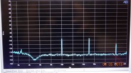
DADOD's DIY amp on another forum at 100W/8, 5KHz THD = .0024%
Pretty nice. BUt the distortion was 10X higher until I rearranged the various grounds... always seems to be a problem with testing.... using isolation transformer on A-P and battery on the PC etc. Then you get lowest data on FFT tests.
Makes me wonder again if distortion will be higher when used in a complete audio system. Thats why I use isolation transformers along with filters on ac line.

THx-RNMarsh
Pretty nice. BUt the distortion was 10X higher until I rearranged the various grounds... always seems to be a problem with testing.... using isolation transformer on A-P and battery on the PC etc. Then you get lowest data on FFT tests.
Makes me wonder again if distortion will be higher when used in a complete audio system. Thats why I use isolation transformers along with filters on ac line.

THx-RNMarsh
Last edited:
Makes me wonder again if distortion will be higher when used in a complete audio system. Thats why I use isolation transformers along with filters on ac line.
View attachment 481093
THx-RNMarsh
Not necessarily, but again, proper grounding and wiring scheme is requested. I use only one PE-AGND connection in the whole system and for sensitive measurements, battery operated notebook. Then, the whole chain, CD-preamp-poweramp has pretty high S/N and very low distortion. And it reflects real conditions.
BTW, very nice result.
I use a massively over-kill ELGAR voltage regulator on the main audio system which isolates it well from all the rest of the house ac line noise and fluctuations.
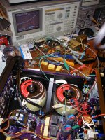
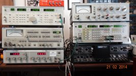
I designed this dual ultra-isolation transformer/filter for others and the filter is > 100dB atten within audio. Excuse the R&D mess on my work bench.

It is used to power and isolate the analog and the digital circuits/equipment.
Then use these to evaluate the non-linearity results without ground and ac power emi/rfi --- very clean system is assured.

Well, it's just a hobby so how serious can one be?
THx- RNMarsh
I designed this dual ultra-isolation transformer/filter for others and the filter is > 100dB atten within audio. Excuse the R&D mess on my work bench.

It is used to power and isolate the analog and the digital circuits/equipment.
Then use these to evaluate the non-linearity results without ground and ac power emi/rfi --- very clean system is assured.

Well, it's just a hobby so how serious can one be?
THx- RNMarsh
Last edited:
FWIW, I did interpret Steve's comment as laughing along with me, not at me.
One of the pernicious effects of listening evaluations is the "different is better" effect. Since, particularly in rapid comparisons, if present, frequency response changes are pretty easy to hear, on level-matched program material one is likely to hear something that may not have been noticed before. This provides fodder for reviewers, who go on about the sound of a certain performance changing between devices, and noticing a particular pluck of a guitar string or resonance in the mid-bass, as if it almost wasn't there before---and conclude that a given device has better resolution etc. Since most amplifiers (say) are rather flat in response and rather low output impedance, they will tend to sound more alike to one another under conditions well below clipping, absent serious defects like severe crossover distortion at low levels. Introduce one that has higher output impedance, or use cables with high inductance/resistance, and you are likely to hear real differences driving the same loudspeakers.
...
I don't quote agree with you on this, Brad. Agreed on frequency response, (relatively) low output impedance, but I think your view that most amps will soud the same until high up in their relative power does not stand. In my experience, the very firt difference you'll find in amps is how loud can they be driven vefore their tonality starts to change, in my view, usually due to either poor PSUs, and/or the manufacturer pushing the output stage near to its limits.
As a perhaps extreme example, I'd quote a power amp by Wangine (Taiwan), rated at 100/150W into 8/4 Ohms using a SEPP with 2SC3281/2SA1302. How you get that kind of power from such a lean output stage is beyond me, but it starts to run out of steam first because of its measily 6,800uF caps. Similar but a bit better with say Onkyo M-282 power amp (SEPP 2SC5200/2SA1943), at least they used 10,000uF caps.
Over the years, I changed a fair number of factory installed 6,800 uF caps in various Technics models for higher values, like 10,000 and 15,000 uF, and each and every time, the device did better, both because 15+ year old caps were replaced by brand new ones, and partly because of the new caps' better regulation due to bigger capacitance.
Obviously, this also greatly depends on the loudspeakers used, in terms on nominal impeance and how awkward it is as a load. My old AR94 speakers, although not as nasty as som other AR models, quickly drains the capabilities of cheap amps' PSUs. On the other hand, loudspeakres in the relative price bracket of cheap amps will tend not to be very forgiving.
Then use these to evaluate the non-linearity results without ground and ac power emi/rfi --- very clean system is assured.
Yes, of course. On the other hand, I am mostly interested in behavior of the real, complete audio chain, under real listening conditions. And it is possible to make it very clean and transparent. I always wonder when guys speak about RFI pick-up and audible radio modulations in a phono + phono preamp setup, something is very wrong, then.
I am also very interested in the whole system... as it tests and sounds. But I dont miss the LP part as I have said often. Tossed it long ago. The A-P will measure jitter and since I drove everyone nuts here going back over and questioning each part of the CD record/play, Jitter is next. BenchMark tells me it is one of the biggest audible problems.
THx-RNMarsh
THx-RNMarsh
Last edited:
Second attempt: This is the phono stage for the Pioneer SA-7700, clone it if you will:
So what about it, John?
In them yore days, companies like Lenco, Dual and quite a few others, normally offered two transistor RIAA eq amps, and it worked fairly well for what they cost. Hardly the last word even for those days, but sounding all right even for way back then.
Economic theory states that the second largest capital investment in most people's lives, after their home, is their car. Please compare the costs of what you were making in those days with car prices of those days. Many of us kew even then that it could all be done much better, we just lacked the wherewithall to buy it. A man could start up a car rental business on the budget of a High End system back then (probaly true even today).
In an ideal system, we would like no currents between grounds of our various gears. This means battery powered low power devices, or Digital optical links, with the DAC included in the power amps.It is used to power and isolate the analog and the digital circuits/equipment.
What do you think ?
Long time ago, i build a compact headphone amplifier, powered both by AC and batteries. I was so surprised to hear the difference when it was working on batteries, everything else the same.
Last edited:
- Status
- Not open for further replies.
- Home
- Member Areas
- The Lounge
- John Curl's Blowtorch preamplifier part II
