I hope you wouldn't mind if I post a slightly off topic question.
For an application similar to a cap multiplier, I need a low noise 15V "Zener" (2 terminal voltage reference).
Dynamic impedance, absolute voltage, and thermal stability are all not so important, only noise.
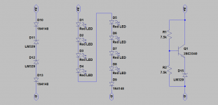
Which one of the 3 in the attachment would you choose, and why ?
Or perhaps ever better suggestions (e.g. a simple Zener // a cap) ?
(I know Samuel likes 1N829A, but they are just unobtainium now ........)
Many thanks in advance,
Patrick
For an application similar to a cap multiplier, I need a low noise 15V "Zener" (2 terminal voltage reference).
Dynamic impedance, absolute voltage, and thermal stability are all not so important, only noise.
Which one of the 3 in the attachment would you choose, and why ?
Or perhaps ever better suggestions (e.g. a simple Zener // a cap) ?
(I know Samuel likes 1N829A, but they are just unobtainium now ........)
Many thanks in advance,
Patrick
Attachments
I hope you wouldn't mind if I post a slightly off topic question.
For an application similar to a cap multiplier, I need a low noise 15V "Zener" (2 terminal voltage reference).
Dynamic impedance, absolute voltage, and thermal stability are all not so important, only noise.
Which one of the 3 in the attachment would you choose, and why ?
Or perhaps ever better suggestions (e.g. a simple Zener // a cap) ?
(I know Samuel likes 1N829A, but they are just unobtainium now ........)
Many thanks in advance,
Patrick
Patrick, what current?
Jan
I hope you wouldn't mind if I post a slightly off topic question.
For an application similar to a cap multiplier, I need a low noise 15V "Zener" (2 terminal voltage reference).
Dynamic impedance, absolute voltage, and thermal stability are all not so important, only noise.
Which one of the 3 in the attachment would you choose, and why ?
Probably the LED chain.
Nothing with gain since that multiplies the noise voltage also. (The problem of the band gap references)
With the chain, the voltages add normally, the voltage noise only with the square root of the devices.
A string of NiCds probably would be the best, but has long-time problems.
Last edited:
Dick has been clear and stated explicitly that he uses the term "distortion" in a non-standard way.
Ah, re-writing the fundamentals to fit the experiment. In this case, the Audio Higgs boson was not found, so we have to abandon the Audio Standard Model.
Can you hear me Major Tom?
If indeed dynamic impedance and stability were no issue, I would also choose LED chain for the reason named, perhaps even add a cap in parallel.
Otherwise I cannot choose between LM329 chain & the "Vbe+LM329" multiplier.
2x LM329 in series is 1.4x the noise of one.
But I can reduce the noise of the multiplier with a cap across the top resistor ??
And then the multiplier is better, at least theoretically ??
I read somewhere that the LM329 becomes unstable when paralleled with a cap.
So no such treatment for the "329 chain" solution.
Patrick
Last edited:
I would like to see how much higher and if combined in other useful ways, also.
Thx-- Richard
Sorry it's lower MUCH lower. Think about it, music has a high crest factor to accommodate peaks you have to have the average voltage level much lower that a full scale sine wave. With simple polynomial distortion the seconds go down as the square, thirds as the cube etc. I just did a numerical sim and you won't like the result. A fully occupied pseudo-random noise signal at the same full scale as a 0 dB sine wave, this is truly music at 11. The second order distortion was applied to be .1% at full scale which gives -66dB THD on the sine wave. The noise floor of the other signal was ~-120dB. The total rms in the sine wave distortion is .00035 and the total rms in the other is .00007.
I could repeat this with music but the result will be even more lopsided. The intuition that some how these distortions all pile up is just wrong.
If indeed dynamic impedance and stability were no issue, I would also choose LED chain for the reason named, perhaps even add a cap in parallel.
Otherwise I cannot choose between LM329 chain & the "Vbe+LM329" multiplier.
2x LM329 in series is 1.4x the noise of one.
But I can reduce the noise of the multiplier with a cap across the top resistor ??
And then the multiplier is better, at least theoretically ??
I think the capacitor would only improve the gained-up part of the total voltage.
Corner frequency would be 0.2 Hz and time to 95% charge 2.25e6 usec
as my RC popup tells me.
> I read somewhere that the LM329 becomes unstable when paralleled with a cap.
> So no such treatment for the "329 chain" solution.
A cap across a low-impedance source is not a good filter since it starts to be good
only where its impedance becomes less than the source. Adding a resistor between
the source and the cap helps, but the thermal noise of the resistor is then against you.
The resistor would also help against the instability.
60 Ohms = 1nV /sqrt Hz, increases geometrically with R. There is an optimum
that is function(reference impedance and noise, cap, wanted noise corner).
Someone should write a spreadsheet.
shunt reg
A look at a more complex circuit in which a JFET is used to develop a reference voltage across a parallel R-C and a simple three-Q shunt regulator is used, with some gain but with another C across the feedback resistor, appears to allow a 10mA 15V shunt regulator with about 400nV rms noise in a 20kHz noise bandwidth, with some uncertainty in the very low frequency noise.
But that's a fair amount of parts. Noise is dominated by error amp e sub n, which at the particular choice of operating current and 50 ohm rbb' devices is about 1.7nV/sq rt Hz per device. Lower rbb' parts and a little more collector current could reduce this further.
I was surprised, recently, to measure some 3.9V 500mW zeners and find their noise lower than I remembered, iirc about 11nV/sq rt Hz. That's really quite good for a standard part and not a buried zener. Probably some slightly higher voltage parts would still be reasonably quiet, and with zeners you are free to bypass with capacitors to your heart's content without fear of instability. 5.1V parts are close to zero tempco as well.
And after 60 years of perfection, they write this:
-quo-
Can you explain negative feedback?
Negative feedback is used to control the amplifier from thermal runaway. This also results in less noise. However, may purists prefer to have as little negative feedback as possible in the signal chain to reduce phase cancellation. With the HA75, you can adjust to suit your personal taste.
-unquo-
Chuckle, chuckle, smile, smile.
Drown these black witches with there warthog anus souls!
Last edited:
FacepalmAnd after 60 years of perfection, the write this:
-quo-
Can you explain negative feedback?
Negative feedback is used to control the amplifier from thermal runaway. This also results in less noise. However, may purists prefer to have as little negative feedback as possible in the signal chain to reduce phase cancellation. With the HA75, you can adjust to suit your personal taste.
-unquo-
Chuckle, chuckle, smile, smile.
When does freedom of expression become over-expanded to the point of culpability?
Out of my parts stock from years back and not easy to identify I'm afraid.> I was surprised, recently, to measure some 3.9V 500mW zeners and find their noise lower than I remembered, iirc about 11nV/sq rt Hz.
Still remember the type & manufacturer ?
Patrick
I had recalled much higher noise in a discussion with dvv, but then remembered that I had been adjusting current in nominal 5.1V parts to get a zero tempco, and this may well have been very suboptimal for noise.
So if 5.1V parts are 15nV/sq rt Hz three in series will amount to about 26nV/sq rt Hz, which is pretty decent for a 15V equivalent.
My point has simply been that DA isn't this hugely frightening audiophile Bogey Man that it's been made into by Richard, John and others over the years.
se
Exactly! Distortion in caps is a problem easily avoided.
However, this does not make it less interesting to ponder the origins of the distortions that may be produced by certain kinds of capacitors (Pavel, thanks for the measurements!). So, in this context, conceivably, non-linear DA could play a role, but it has not been proven to exist, the material, nor the phenomenon in other than a metaphysical sense.
At the same time, even if it would exist, non-linear DA could never play a role in audio because of the time scales involved. DA is a slow process, this is also how it is measured. From Wikipedia:
Dielectric absorption is a property which has been long known. Its value can be measured in accordance with the IEC/EN 60384-1 standard. The capacitor shall be charged at the DC voltage rating for 60 minutes. Then the capacitor shall be disconnected from the power source and shall be discharged for 10 s. The voltage regained on the capacitor terminals (recovery voltage) within 15 minutes is the dielectric absorption voltage. The size of the dielectric absorption voltage is specified in relation to the applied voltage in percent and depends on the dielectric material used.
Introduce time constants of this magnitude in the RC model for DA, and it becomes clear that any effect on audio-frequencies cannot exist, me head sim says.
BTW, nice old school standard for DA, and not one that lends itself very well to finding non-linearities. It's a bit like defining the inductance of a coil by sending a set current through it, and then measuring the length of the spark it produces after disconnect. Pretty primitive all.
Last edited:
Sorry it's lower MUCH lower. Think about it, music has a high crest factor to accommodate peaks you have to have the average voltage level much lower that a full scale sine wave. With simple polynomial distortion the seconds go down as the square, thirds as the cube etc. I just did a numerical sim and you won't like the result. A fully occupied pseudo-random noise signal at the same full scale as a 0 dB sine wave, this is truly music at 11. The second order distortion was applied to be .1% at full scale which gives -66dB THD on the sine wave. The noise floor of the other signal was ~-120dB. The total rms in the sine wave distortion is .00035 and the total rms in the other is .00007.
I could repeat this with music but the result will be even more lopsided. The intuition that some how these distortions all pile up is just wrong.
Ok. Thats a good demo test. I was thinking more along the lines of .1% plus another .1% plus another .1% etc. Like a string of ceramic caps/parts might produce or a string of stages in an amplifier.... combining......Increasing slightly. No?
-RM
Ok. Thats a good demo test. I was thinking more along the lines of .1% plus another .1% plus another .1% etc. Like a string of ceramic caps/parts might produce or a string of stages in an amplifier.... combining......Increasing slightly. No?
-RM
Gain structure, what chain would have every stage running at full scale? Even then it's only 6db per stage. So we're not just talking a single use like crossover or RIAA anymore, and you are not moving the goal posts?
Last edited:
Dick has been clear and stated explicitly that he uses the term "distortion" in a non-standard way.
That is absolutely correct. I have never written about non-linearity and never measured it in caps. I wrote for a lay public and referred to the waveform change as a distortion of the original .. under the specific test conditions shown.
Non-linearity was however measured extensively by W.Jung and presented in the Audio magazine expose on all sorts of parasitics of caps.
JC did tests and did with W.Jung. A comparison test with various dielectrics.
I think your collective imaginations have got the better of you as have cable builders and wire makers and boutique cap seller who talk about their materials [with silver or gold leads, ofc copper and on and on] and related it to DA and non-linearities which they know even less than most anyone does in various ways as to why thier product is better ---- has nothing to do with the original subject.
So we went from trying to rid the worst offender in the way to amp lower distortion - the alum electrolytic (polar) cap to this marketing material craziness and hype. If it's all my fault, then I want to get a cut of all the money made.
THx-RNMarsh
- Status
- Not open for further replies.
- Home
- Member Areas
- The Lounge
- John Curl's Blowtorch preamplifier part II