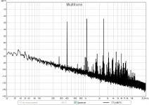
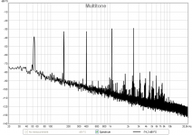
How about a nice multi-tone showing how IM raises apparent noise floor?
Speaker distortion
There were claims, several times, in this thread, that speaker distortion is of mostly 2nd and 3rd harmonic components and that high order harmonics of power amplifiers would be higher in level than those of the speaker. I would like to demonstrate that this is completely untrue, for at least moderately well designed power amplifier.
First, statements about only 2nd and 3rd in speaker spectra most probably originate from resolution of methods used decades ago. Second, many contemporary authors, like Wolfgang Klippel, have shown that distortion in speakers is influenced by many factors and is very complex, not restricted to 2nd and 3rd.
Measuring intermodulation distortions would show us complexity of speaker distortions, but we can see a lot in a single sine distortion with appropriate resolution.
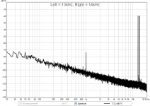
I have shown, in this thread a measurement of a midrange driver at 2kHz and about 2Vrms and was told that high order distortion components are a product of the measuring microphone and I was suggested to use a compressed air to clean it. Nice shot, but out of the target. As a proof, I am demonstrating a CCIF 13+14kHz of the tweeter. It was measured with 2 speakers by 2 different test signals.
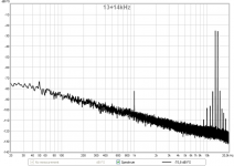
First signal was pure 13kHz feeding left speaker and 14kHz feeding right speaker. Thus, there is no intermodulation in tweeters, only in a measuring microphone. We can see, in the measurements shown, that there is a difference tone, i.e. 2nd harmonic component, in the microphone channel output. But, no 3rd, 5th, 7th etc. No skirts. In the second measurement, only the left speaker was driven, with 13+14kHz twin tone signal. Now, we can see not only the 2nd harmonic, but also the skirts of 3rd, 5th, 7th and 9th. These are tweeter odd harmonics intermodulation products. Not microphone products. Just to mention that system intermodulation (electrical circuits) is invisible in this scale.
I have made a set of multitone measurements of speakers: 3-tone, 5-tone, speech, ITU_T 0.81, low decade, high decade ….., so if anyone is interested, I can post more plots.
Attachments
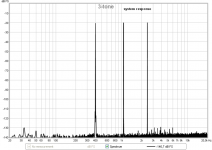
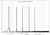
Pavel, how did you determine the system electrical responses - was this measured at the speaker terminals, at the same time as the speaker responses were taken?As a start, 3-tone and 5-tone speaker responses compared to system electrical responses.
Speaker distortion
First signal was pure 13kHz feeding left speaker and 14kHz feeding right speaker. Thus, there is no intermodulation in tweeters, only in a measuring microphone. We can see, in the measurements shown, that there is a difference tone, i.e. 2nd harmonic component, in the microphone channel output. But, no 3rd, 5th, 7th etc. No skirts. In the second measurement, only the left speaker was driven, with 13+14kHz twin tone signal. Now, we can see not only the 2nd harmonic, but also the skirts of 3rd, 5th, 7th and 9th. These are tweeter odd harmonics intermodulation products. Not microphone products. Just to mention that system intermodulation (electrical circuits) is invisible in this scale.
Excellent test methodology.
Thank you very much Pavel
George
Nah, the kids would recognise that and tell me off. Shame I didn't get a picture of the xmas catcus (Schlumbergera)in bloom as that is another cutting off a mother plant that may be older than me. But here is it in all its glory.
Better use of my time to upload that than argue modulation noise...
Here's one off mine last year I think
")
https://www.flickr.com/photos/england78/8626298385/in/set-72157631925164690
Excellent test methodology.
Thank you very much Pavel
George
You are welcome, George.
> Not many P channel in production right now, ....
But you can still get NOS 2J74 in China, if you look hard enough and are prepared to pay.
Also there is a market there for 2nd hand FETs (they say removed from equipment).
So not everything is fake from China. You jut need to know how to distinguish.
Patrick
But you can still get NOS 2J74 in China, if you look hard enough and are prepared to pay.
Also there is a market there for 2nd hand FETs (they say removed from equipment).
So not everything is fake from China. You jut need to know how to distinguish.
Patrick
As a start, 3-tone and 5-tone speaker responses compared to system electrical responses.
Thanks for testing.
This all looks quite familiar, an increasing floor of modulation components orders of magnitude greater than from electronics. In short, speakers produce lots of modulation noise.
Andrew
This was 3-way. Vrms <2V
Results are quite consistent with different speakers.
There is a rule, 3-way has less distortion than 2-way and 2-way less than fullrange. Smaller woofer has higher LF distortion than bigger woofer.
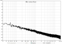
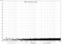
Pavel where does the rising noise floor come from?
Scott, please see microphone input (preamp, open input) noise floor itself and the same with phantom-powered ECM8000 connected. IMO it is the capsule noise + noise of electronics integrated in the ECM body.
Attachments
Scott, please see microphone input (preamp, open input) noise floor itself and the same with phantom-powered ECM8000 connected. IMO it is the capsule noise + noise of electronics integrated in the ECM body.
That certainly makes sense but an isolation chamber would give a definitive answer but this certainly is not a problem in proving your point.
What I would like to know is what mechanism creates any significant amount of higher order harmonics from a loudspeaker, itself? Of course, Xover distortion, the REAL PROBLEM, is almost completely power amp generated, with IC's coming in a close second.
Of course, there are better amps that don't have xover distortion. I try to make them when I can, and you do too, PMA, but most here would not bother to, and would say that it is not worth the time and cost to make amps of this quality. That is the fundamental argument debated here.
Of course, there are better amps that don't have xover distortion. I try to make them when I can, and you do too, PMA, but most here would not bother to, and would say that it is not worth the time and cost to make amps of this quality. That is the fundamental argument debated here.
What I have hoped to address on this thread from the beginning, is more than whether X-over or TIM distortion is important in audio design. I found these answers for myself back in the 1970's, but I have learned that there is more to it to make a really successful audio electronic design. Parts linearity, wire quality, case integrity, and even the amount of overall global negative feedback can be important in a really successful design. Unfortunately, I had to learn this though trial and error, personal listening experience and finally world acceptance of a never seriously advertised product.
Now where does this simple, cost effective JC-2 line amp copy (the electronics at least) become useful?
This inexpensive preamp uses the essential original topology that I found almost universally successful, more than 40 years ago, and still pretty good today. Think about it as a copy of a much older Porsche, maybe even a 356 or very early 911. IF China could make and sell one for $5000 or so, we might find it a real bargain! But why would we start with such a copy? Because it was designed with 'experience' derived from years of motor racing and personal feedback. It wouldn't be perfect, but it might have that 'magic' that made Porsche famous, and for good reason, if the original concepts are copied well. I hope the same for this JC-2 copy, not expecting perfection, but still retaining the essence of the JC-2 line stage from 40 years ago, and comparing it to similar priced IC based designs of today. Let's try it!
- Status
- Not open for further replies.
- Home
- Member Areas
- The Lounge
- John Curl's Blowtorch preamplifier part II