Scott’s link is excellent.
Here is the standard method used for measuring that noise (there are some important details in there)
http://www.landandmaritime.dla.mil/Downloads/MilSpec/Docs/MIL-STD-202/std202mthd308.pdf
You mean perception wise on an analog set?
Judging from listening to vintage tube gear, not a very bad effect.
On a high resolution ADC it will eat-up a few lower bits of resolution, masking the very low level details (if any were there).
On a 16 bit ADC either no effect or it will manage to affect the LSB.
Number of Bits/ Number of Steps/Step height (Resolution) in uV for 2V FS (*)
8/256/7812.5
16/65536/30.52
20/1048576/1.91
24/16777216/0.12
George
(*) This is the theoretically maximum resolution (no overhead)
Here is the standard method used for measuring that noise (there are some important details in there)
http://www.landandmaritime.dla.mil/Downloads/MilSpec/Docs/MIL-STD-202/std202mthd308.pdf
What affect would the higher noise at low freq have on operation at mid and higher freqs??
You mean perception wise on an analog set?
Judging from listening to vintage tube gear, not a very bad effect.
...On a high resolution audio ADC ??
On a high resolution ADC it will eat-up a few lower bits of resolution, masking the very low level details (if any were there).
On a 16 bit ADC either no effect or it will manage to affect the LSB.
Number of Bits/ Number of Steps/Step height (Resolution) in uV for 2V FS (*)
8/256/7812.5
16/65536/30.52
20/1048576/1.91
24/16777216/0.12
George
(*) This is the theoretically maximum resolution (no overhead)
Last edited:
Judging from listening to vintage tube gear, not a very bad effect.
Many noisy stuffs are actually sound "organics", "natural", "musical". I don't think it is because of the noise itself, but I guess (at least mostly) because of other physical/mechanical properties that allow for noise as the compensation. For example, a circuit can be so simple such that phase behaviour is good but PSRR is poor and thus noisy.
In case of carbon composition resistor, I don't know how they are produced, but I believe there is something that makes them sound like they do (May be carbon is just a good material for the purpose and then some).
In a CRC power supply filter for tube amps, the resistor undergoes consistent voltage drop for a long time. At the end of the day, the resistor becomes noisier , can be clearly heard when you use it for other functions, such as L-PAD for tweeter crossover.
I believe CC resistors are made by baking a mixture of fine carbon particles and clay. The result is unstable over long time periods and with temperature changes, noisy over short time periods and somewhat non-linear. Just what some people seem to prefer for audio!Jay said:In case of carbon composition resistor, I don't know how they are produced, but I believe there is something that makes them sound like they do
In olden days this is all we had. Now we have much better resistors. CC are only made now because they are much better at handling short-term power transients, which would blow up a film resistor with the same average power rating.
Yes, many thanks guys for digging up these references.very nice link and the reference that Scott gave tells all by brand and thin/thick/smd/th. Very nice.
I didnt test for as many brands on a Quan-Tech resistor noise test instrument I have here but similar results.
Ok, I just did a quick and dirty experiment in Cool Edit.What affect would the higher noise at low freq have on operation at mid and higher freqs?? ...On a high resolution audio ADC ??
THx-RNMarsh
I generated a pink noise signal and then low pass filtered it with 15Hz 4th order cutoff freq.
I then mixed this at relatively low level signal with a known music track and listened on my B mini system out here in the sunroom.
The result is akin to what I get with BQP or my other filter on my A system....ie adding the low freq noise signal to the music signal is analogous to removing BQP or my other filter on my A system.
The noise signal is not really directly audible from my listening position across the sunroom, BUT adding this noise signal subjectively reduces the overall perceived sound level and dynamics, reduces the low bass and messes mids and highs....this effecting/affecting (inversely) correlates with experiences on my A system.
Now, in this case I am dealing with first order effects, ie mixing/adding and I am not really adding modulation/secondary effects such as dynamic THD, IMD or PMD (jitter like) effects.
This all ties in with my experiences to date with BQP and my filter....reduce conductor noise and a whole cloud of secondary effects shite is exponentially reduced.
Subjectively the result is much more realistic dynamics, bass that extends down to the floor, mids clearer/cleaner and highs extended.
By treating (noise reduction) both signal channels together plus power reduces L/R dynamic errors with result of pin sharp lateral imaging and pin sharp depth imaging....as is to be expected.
Excess 1/f noise production is dynamic in nature in a typical circuit using typical componentry...the typical result is the subjective sorry mess as per most listeners experience.
Utilising very low noise componentry goes a long way to providing clean audio reproduction, reducing conductor LF noise takes things to the next level.
Notably Jfets exhibit very low 1/f current noise.....iow, JC ain't stupid.
Dan.
Low-Noise JFETs — Superior Performance to Bipolars
Last edited:
.iow, JC ain't stupid.
No, he's not. His promotion of fraud cannot be attributed to stupidity.
''Excuse me the record's stuck, the record's stuck, the record's stuck, the record's stuck, the record's stuck, the record's stuck..."No, he's not. His promotion of fraud cannot be attributed to stupidity.

Dan.
Dan, it's always a serious challenege for me to explain my power conditioners don't remove artifacts that are audible, identifiable, but rather they remove noise that modifies the music you do hear. (Or worse, explaining to a musician it can only make the sound they like better, as they fear it'll change their type of sound and can't comprehend a quality difference to a type of sound.... or they say, "great I hate buzzing ground noise" which it has no affect on their janky wired guitar)
Your inverse experiment of adding noise to test similarity affect to removing a filter is a wonderful idea.
Side note,
Your inverse experiment of adding noise to test similarity affect to removing a filter is a wonderful idea.
Side note,
noisy over short time periods and somewhat non-linear. Just what some people seem to prefer for audio!
Hehe, it is for a good reason!
In olden days this is all we had. Now we have much better resistors. CC are only made now because they are much better at handling short-term power transients, which would blow up a film resistor with the same average power rating.
I believe there are many types of carbon resistors. Nowadays it is confusing because the external are similar but the sound is different. I still have some stocks of what I believe a CC resistors (because they sound like vintage Allen-Bradley). They are 1/4W size. The brand is Motorola. Several pieces (about 20 or less) in one plastic package. Every time I build amps with them (even only used in feedback), when I listened, I stood there speechless for minutes. But the details are missing (or the opposite, depends on how you see it)
Side note (I forgot)
If your stereo when playing something panned hard or full right/left, doesn't leave you confused to whether or not it's coming from the speaker because it projects a bodied shape that isn't like the speaker, you're probably suffering some kind of poor equipment that's not up to snuff. Having a soundstage that makes people believe there is a center channel isn't that hard, but having it be compelling with authority is harder. Well it's easy actually, but a lot of gear isn't very good with it.
If your stereo when playing something panned hard or full right/left, doesn't leave you confused to whether or not it's coming from the speaker because it projects a bodied shape that isn't like the speaker, you're probably suffering some kind of poor equipment that's not up to snuff. Having a soundstage that makes people believe there is a center channel isn't that hard, but having it be compelling with authority is harder. Well it's easy actually, but a lot of gear isn't very good with it.
Extra thanks gpapag for the 'co-design---" noise link. Truly excellent and intuitive, much like early AES papers (pre-1980) were. I have been half asleep on this issue, since we shifted from carbon comp to thin film, about 40 years ago. I am under constant pressure to use more surface mount resistors, and now I know what to look for (noise-wise) in the modern surface mount resistors. It is not a surprise, but a reminder to me to be very careful what you select as an audio part.
About carbon resistors http://allserv.kahosl.be/~wim.degeest/5.2 Weerstanden 1.pdf
In here it says
And that Google-translates into
In here it says
Koolfilmweerstand : Op een keramische drager wordt een homogene koollaag aangebracht
(bvb. door pyrolyse). De keramische drager is goed isolerend, mechanisch stevig, verdraagt
gemakkelijk temperatuursvariaties en leent zich gemakkelijk tot verdere bewerkingen.
In de koollaag wordt een schroeflijnvormige groef gesneden (helixing) waardoor de
weerstandswaarde binnen de tolerantiegrenzen gebracht wordt. Hoe dunner de koollaag en
hoe kleiner de steek van de schroeflijn, des te groter de weerstandswaarde.
Op de uiteinden van het weerstandslichaam worden metalen doppen (caps) geperst waaraan
vertinde draden van elektrolytisch koper worden gesoldeerd. Achteraf worden meerdere
beschermende laklagen aangebracht. (fig 1.6)
And that Google-translates into
Kool Film Resistance : On a ceramic substrate a homogeneous carbon layer is applied
(eg . by pyrolysis) . The ceramic substrate is well insulated , mechanically strong , endure
temperature variations and easily lends itself easily to further processing.
In the carbon layer is a helical groove cut ( helixing ) to give the
resistance value shall be within the tolerance limits . The thinner the coal seam and
the smaller the pitch of the helical line , the greater the resistance value.
At the ends of the resistance body are metal caps (caps ) are forced to which
tinned electrolytic copper wires are soldered . Afterwards be more
protective coatings applied . (Fig 1.6)
Last edited:
Ok, I just did a quick and dirty experiment in Cool Edit.
I generated a pink noise signal and then low pass filtered it with 15Hz 4th order cutoff freq.
I then mixed this at relatively low level signal with a known music track and listened on my B mini system out here in the sunroom.
Dan.
Low-Noise JFETs — Superior Performance to Bipolars
Conversely, if you limit the freq response to eliminate the 1/F noise ----- like 20Hz-40Hz range, you get cleaner over-all sound.... but then group delay and what-ever else has to be controlled. You can try that experiment also and listen. But, in the end, just dont produce significant 1/f noise in the first place is better (cost not considered).
THx-RNMarsh
Perhaps we have a 'quorum' of designers to make talking about 'line conditioners' practical and useful. I am now testing the latest Bybee line conditioner (now out of production), the successor of a number of earlier, sometimes much more complex, line conditioners.
Richard Marsh and Demian Martin have a good deal of experience with designing them. Then, last but not least, the rest of you who have contributed here recently.
I might start with which may be obvious to many here: Power lines are often very noisy, and are getting noisier due to more switching power supplies loading the line, etc. Sometimes line conditioners can be VERY USEFUL and in other locations, hardly useful at all. Just depends on the local conditions.
Last edited:
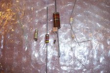
Carbon resistors exist in at least 3 flavors: the oldest is a sintered rod made of a mix of carbon, mineral binder and filler. Exists with metallized, tinned and soldered terminations or pressed brass machined ends.About carbon resistors
The "Carbon Composition" type is based on thermoset compounds: pure for the outer envelope, and mixed with carbon and filler for the active inner part.
Carbon film are the ones described by Fdw.
From left to right:
-A relatively recent example of sintered rod (earlier types were much older, >60years ago, and much larger)
-4 examples of carb-comp, including the ubiquitous 1/2W, a rarer parallelipedic type, a 1W, and one of the nastier example: a 10 Meg-1/8W (which has probably drifted to 15 Meg, in spite of its very optimistic 5% tolerance)
-3 examples of carbon film resistor; quite stable and reliable compared to the two other types
Attachments
Last edited:
I might start with which may be obvious to many here: Power lines are often very noisy, and are getting noisier due to more switching power supplies loading the line, etc. Sometimes line conditioners can be VERY USEFUL and in other locations, hardly useful at all. Just depends on the local conditions.
Do you think that it might be useful to measure the analog output spectrum of well-engineered audio gear with and without line conditioners to see if there really is any significant effect, and if so, what the root causes are? Just because something shows up on a power line doesn't mean that it causes problems in a box of gain plugged into it. Or maybe it does- data specific to the application might help establish that and to quantify the relative efficacy of various proposed solutions.
Passive conditioners are a joke compared to active types: an example at work here:Perhaps we have a 'quorum' of designers to make talking about 'line conditioners' practical and useful. I am now testing the latest Bybee line conditioner (now out of production), the successor of a number of earlier, sometimes much more complex, line conditioners.
Richard Marsh and Demian Martin have a good deal of experience with designing them. Then, last but not least, the rest of you who have contributed here recently.
http://www.diyaudio.com/forums/equipment-tools/266421-power-oriented-cap-meter.html#post4159514
It not only works for high frequencies, but it is equally capable of removing mains harmonics, including the lowest, like second and third, and even subharmonics, or other signals high or low in frequency: basically it kills everything that isn't 50 or 60Hz. And it is not even bulky...
Do you think that it might be useful to measure the analog output spectrum of well-engineered audio gear with and without line conditioners to see if there really is any significant effect, and if so, what the root causes are? Just because something shows up on a power line doesn't mean that it causes problems in a box of gain plugged into it. Or maybe it does- data specific to the application might help establish that and to quantify the relative efficacy of various proposed solutions.
I am absolutely sure this will never happen. You will hear stories, instead.
I am absolutely sure this will never happen. You will hear stories, instead.
Well, if you don't ask...
- Status
- Not open for further replies.
- Home
- Member Areas
- The Lounge
- John Curl's Blowtorch preamplifier part II