Stan Ricker is free-lance and he has worked with just about everybody. He worked with Mobile Fidelity, Sheffield in the the 'Moscow Sessions', and on the Wilson Audio recordings, for example. So far as I know, he is usually the chosen engineer for cutting the record, rather than the recording engineer.
Keith Johnson is a recording engineer as well as a design engineer. Perhaps, we can get a book out of him, too. I would certainly read it.
Keith Johnson is a recording engineer as well as a design engineer. Perhaps, we can get a book out of him, too. I would certainly read it.
Bringing back these old memories of pro audio design, to me, I thought that I might comment on what I used for building blocks for pro audio. One building block was a discrete op amp design that I used for Crystal Clear, Mobile Fidelity, and Wilson Audio.
This was a fairly conventional design, because it was designed before Toshiba made their complementary series of low noise J-fets.
This sort of design is popular here today, but I first made it in 1977 for Crystal Clear records. It was composed of an N channel dual fet input, fed by a two terminal current source. The second stage was a quad of complementary matched low noise transistors, and the output was a pair of complementary J-fets, biased by crossing the gates to the opposite sides of a small pot, so that I could control the output bias current to about 15ma.
The only real difference between this module and an IC, was the beta multipliers on each supply, both + and -. This kept any interaction from adjacent channels from modulating each module. This, I found very important.
I first made an 8 channel mike preamp and mixer for Crystal Clear, with these modules.
Later, a couple of master recorder electronics for Mobile Fidelity, and finally, the 'Ultramaster' for Dave Wilson.
This design was a real 'workhorse' for me, for about 7 years. It could be made more quiet, by replacing the input J-fets with Toshiba devices as they became available, and with output V-fets for more current drive.
The real advantages of this discrete device, over IC's, was lower noise over a wide impedance range, class A through-out, and individual buffering of the power supplies.
The real advantages of this discrete device, over IC's, was lower noise over a wide impedance range, class A through-out, and individual buffering of the power supplies.
How did you buffer the power supplies?
Well, I've been playing with shunt regulators and build one with feedback and one without. I've just been using a wall wart to test them for now. Anyway, I had a CCS like this (except this is current sink, not a source obviously) driving some zeners for the passive regulator, no feedback one.
And, with a RC filter at the output the noise is very low < -120dB with respect to one volt RMS. I was surprised, but funny thing is that it has a lot of hum sometimes. But if I grab the wall wart positive supply wire with my fingers the hum goes away. I'm not grounded either and my chair has insulated feet.
Only thing I can think of would be inductance of my fingers. When the power supply and or circuit warms up, the hum usually goes away. But not always.
I found both active and passive regs do the same thing when I grab the wire. Except the the active has more hum, but it has no RC filter at the output. Both have about the same high frequency performance, best I can tell, since it's lower than I can measure right now.
I might try some ferrite bead on the positive line. Adding more filter capacitance actually made the hum much worse.
I not that experienced with this stuff ... just thought this was interesting that just touching the wire made such a difference at 60Hz.
I am a little more practical, in that I used series regulators composed of a single transistor, one resistor and 3 caps, to electrolytic and one film. Just a cap multiplier that both quiets the power supply noise and buffers individual modules from each other.
It is very efficient, using less than 2V of rail per side and not increasing the current consumption that can really add up, when everything else is class A, and you have lots of modules.
There is nothing wrong with a shunt regulator, I use one pair for each channel in the Blowtorch, but I also have two series regulators as well, per supply line.
When I started making the Vendetta Research phono stage, I had to severely change the design to remove the output cap (electrolytic) because my power supply rejection was very poor in my comp folded-cascode j-fet input stage.
We did an A-B, and I realized that caps could be audible in the power supply lines. What a drag. I had to design the entire circuit board.
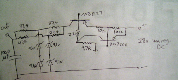
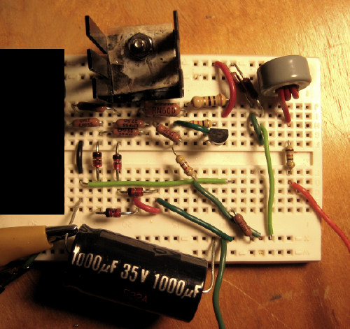
I just drew the circuit up real quick. There is a 7k resistor at the output, and a 4k resistor across the output of the unregulated 28 volt DC wall wart which I forgot to draw. The MJE271 is a Darlington, just too lazy to draw it.
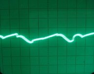
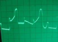
Here is the hum, though it's usually about 2 or 3 times worse than what I photographed.
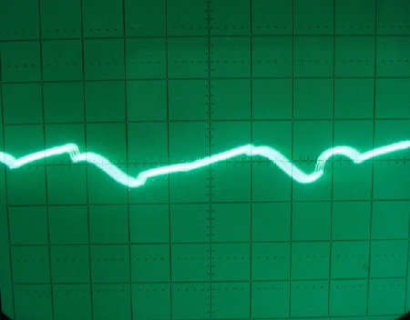
And after I grab the wire of the 28 volt supply. The hum is -115dB here, I'm not sure what it is before I grab the wire.
Well, a pretty simple circuit and I got more work to do. The unregulated power supply ripple is 0.2 volts peak.
Here is the hum, though it's usually about 2 or 3 times worse than what I photographed.
And after I grab the wire of the 28 volt supply. The hum is -115dB here, I'm not sure what it is before I grab the wire.
Well, a pretty simple circuit and I got more work to do. The unregulated power supply ripple is 0.2 volts peak.
Attachments
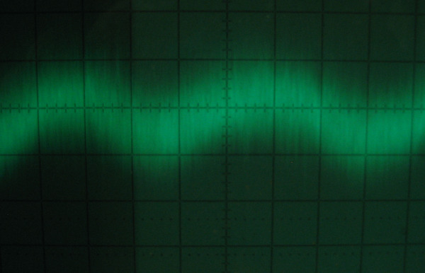
Thanks John, I tried reducing the 27.4 ohm resistors to 12 ohms and that did cut the hum by about half. The pictures I posted before didn't really catch how bad this hum often is, and the 0.2 volts ripple from the wall wart supply doesn't change either. So, there is some other problem there. This is at 0.2 volts/div after being amplified by 4,300. Hum is -84dBv.
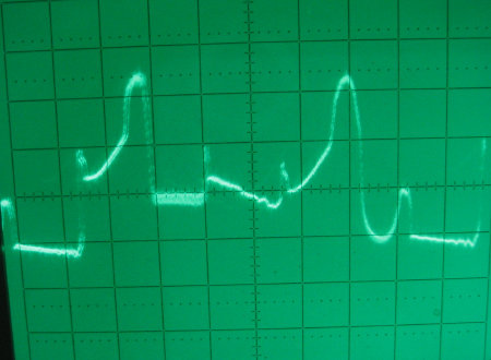
I also had a 47.5 ohm resistor in series with the positive output of the wall wart just before the reg input, which I forgot to draw in. I put that there when reg current was only 20mA with the active shunt, but at 70mA passive it was costing me 3.3 volts. I reduced that series resistance to 12 ohms and the hum got worse.
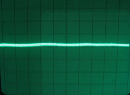
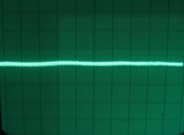
Then I put 0.1mH of inductance in place of that resistor and got this, at 0.01 volts/div. Hum is -115dB.
Anyway, not sure what the deal is. But, the inductor seems to have fixed it.
I also had a 47.5 ohm resistor in series with the positive output of the wall wart just before the reg input, which I forgot to draw in. I put that there when reg current was only 20mA with the active shunt, but at 70mA passive it was costing me 3.3 volts. I reduced that series resistance to 12 ohms and the hum got worse.
Then I put 0.1mH of inductance in place of that resistor and got this, at 0.01 volts/div. Hum is -115dB.
Anyway, not sure what the deal is. But, the inductor seems to have fixed it.
Attachments

I was surprised, but funny thing is that it has a lot of hum sometimes. But if I grab the wall wart positive supply wire with my fingers the hum goes away. I'm not grounded either and my chair has insulated feet....
Only thing I can think of would be inductance of my fingers. When the power supply and or circuit warms up, the hum usually goes away. But not always.
I found both active and passive regs do the same thing when I grab the wire. Except the the active has more hum, but it has no RC filter at the output. Both have about the same high frequency performance, best I can tell, since it's lower than I can measure right now.
I might try some ferrite bead on the positive line. Adding more filter capacitance actually made the hum much worse.
I not that experienced with this stuff ... just thought this was interesting that just touching the wire made such a difference at 60Hz.
For my money, it's oscillating at some very high frequency, which is why the effect of your finger's presence can make such an effect. 50/60Hz is effectively unaffected by such a small capacitance/inductive change, but 200MHz can be wildly affected.
Why VHF oscillation is audible at the local mains frequency I have no idea, but I first had this effect 30 years ago on a preamp stage that had ABSOLUTELY DC supplies. And some low level hum. The hum vanished when I added grid stoppers to the CF output stage, and obvioiusly killed an oscillation too high to be seem on my (then) 20MHz scope.. This has been a stable datum for me ever since, anything weird, especially weird hum that's affected by hand capacitance, first check for VHF oscillation.
Regards, Allen
For my money, it's oscillating at some very high frequency, which is why the effect of your finger's presence can make such an effect. 50/60Hz is effectively unaffected by such a small capacitance/inductive change, but 200MHz can be wildly affected.
I would support that.
I had similar troubles in diamond buffers, local oscillations at 250MHz, of some 10-20mV. It was detected by 3GHz spectrum analyzer, and as a secondary effect there was a hum increase.
@Johnloudb
Convert that circuit into emiter follower (change MJE... for NPN).
Use different biasing for 2N3906, right now you are feeding noise into it's base.
2N3906 should drive voltage reference at base of output transistor.
If you are using noisy Zeners as voltage reference, filter Vref through RC filter before driving base of output transistor. You will enjoy more")
And load output with few mA to lower output impedance. Resistor + LED will be OK, you got working indicator for free
Convert that circuit into emiter follower (change MJE... for NPN).
Use different biasing for 2N3906, right now you are feeding noise into it's base.
2N3906 should drive voltage reference at base of output transistor.
If you are using noisy Zeners as voltage reference, filter Vref through RC filter before driving base of output transistor. You will enjoy more
And load output with few mA to lower output impedance. Resistor + LED will be OK, you got working indicator for free
@Johnloudb
Convert that circuit into emiter follower (change MJE... for NPN).
Use different biasing for 2N3906, right now you are feeding noise into it's base.
2N3906 should drive voltage reference at base of output transistor.
If you are using noisy Zeners as voltage reference, filter Vref through RC filter before driving base of output transistor. You will enjoy more
And load output with few mA to lower output impedance. Resistor + LED will be OK, you got working indicator for free
John,
Your scope pics show (apart from the low level hash) charging current pulses from rectifiers - don't know exactly what your setup is but it appears you have a ground issue. Seems there's some common grond wiring/tracks shared by both the supply and the signal grounds. Possibly the return leads to supply caps or the return to the wall-wart?
jd
sample of one
Wilson Audiophile vinyls seem to fetch premium prices on Ebay.
This one interested me when the bid was about $41. Winning bid $202.50. (However, I am not really setup with a vinyl player.)

"The People Involved In This Project Reads Like A Hall Of Fame : John Curl (Of Mark Levinson Fame) Designed The Recorder; Stan Ricker Did The Mastering, Teldec Did The Pressing, And The Whole Enterprise Was Auditioned Through Wilson WATTs And WAMMs, Utilizing Spectral Electronics From Keith Johnson (Reference Records) ."
.
Wilson Audiophile vinyls seem to fetch premium prices on Ebay.
This one interested me when the bid was about $41. Winning bid $202.50. (However, I am not really setup with a vinyl player.)
"The People Involved In This Project Reads Like A Hall Of Fame : John Curl (Of Mark Levinson Fame) Designed The Recorder; Stan Ricker Did The Mastering, Teldec Did The Pressing, And The Whole Enterprise Was Auditioned Through Wilson WATTs And WAMMs, Utilizing Spectral Electronics From Keith Johnson (Reference Records) ."
.
Thanks for all the help guys.
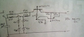
Yes, glad you pointed that out. I put a 221 ohm resistor in series with the base.
It's breadboarded, but I cleaned up the layout and star grounded. I think it helped a bit with HF noise but hard to tell, since it is close to the noise floor of my measurement setup. Other than the slight hum, I can now see no difference between the noise floor of measurement setup and the output of circuit.
I couldn't see any oscillation on my 100MHz scope, but it can be hard to see ringing sometimes.
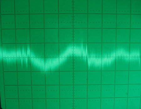
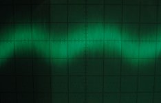
Here is what it looks like now.
Only thing that really works to stop the hum is the 0.1mH ferrite bead choke. So, I think you might be right Hitsware, about the demodulated high frequency noise causing the hum problem.
In any case I think it works pretty good now. Or maybe I'm just easily satisfied? Thanks for the all input guys.
John
stormsonic said:Use different biasing for 2N3906, right now you are feeding noise into it's base.
Yes, glad you pointed that out. I put a 221 ohm resistor in series with the base.
janneman said:John,
Your scope pics show (apart from the low level hash) charging current pulses from rectifiers - don't know exactly what your setup is but it appears you have a ground issue. Seems there's some common grond wiring/tracks shared by both the supply and the signal grounds. Possibly the return leads to supply caps or the return to the wall-wart?
It's breadboarded, but I cleaned up the layout and star grounded. I think it helped a bit with HF noise but hard to tell, since it is close to the noise floor of my measurement setup. Other than the slight hum, I can now see no difference between the noise floor of measurement setup and the output of circuit.
I couldn't see any oscillation on my 100MHz scope, but it can be hard to see ringing sometimes.
Here is what it looks like now.
Hitsware said:Also hum can ride in on RF and then be demodulated by xisistor junctions.
Only thing that really works to stop the hum is the 0.1mH ferrite bead choke. So, I think you might be right Hitsware, about the demodulated high frequency noise causing the hum problem.
In any case I think it works pretty good now. Or maybe I'm just easily satisfied?
Thanks for the all input guys.John
Attachments

about recorders
The Sony PCMD50 96 kHz/24-bit recorder is a decent portable recorder? Low noise levels are dependent on the quality of microphones. The recorder up from this--the Sony PCM-D1--uses Scott's AD797s.
Amongst other things, I have in mind things like what Bear wrote about comparing mic'ed live (outside ambient) versus recorded ambient.
-
For not much more, the Korg MR-2 records DSD (that can be save to a SA-CD format).

.
The Sony PCMD50 96 kHz/24-bit recorder is a decent portable recorder? Low noise levels are dependent on the quality of microphones. The recorder up from this--the Sony PCM-D1--uses Scott's AD797s.
An externally hosted image should be here but it was not working when we last tested it.
Amongst other things, I have in mind things like what Bear wrote about comparing mic'ed live (outside ambient) versus recorded ambient.
-
For not much more, the Korg MR-2 records DSD (that can be save to a SA-CD format).
.
Last edited:
- Status
- Not open for further replies.
- Home
- Member Areas
- The Lounge
- John Curl's Blowtorch preamplifier part II