For transverse mode noise the transformer transmission is what matters. The usual passband with resonant notches is what you will see. There are transformers designed to control the bandwidth and suppress noise and surges. ONEAC’s isolation transformers are a good example http://www.gryphon-inc.com/Spec Sheets/935012E - Product Selection Guide.pdf . But they won’t do much for common mode noise.
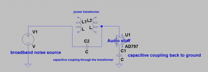
Let me try to explain why the transformers performance matters little to the common mode noise problem. The drawing below should illustrate it. Typically there is a fair amount of common mode noise on the line from emi/rfi and even power line communications. The cables in the wall and in your system can also pick up radiated noise. It may have started as transverse mode but after a few hundred feet or more there is energy between all three wires. That energy is pretty high impedance. What that means is that a series impedance won't reduce the current.
Maybe this explanation will be clearer than mine. The drawings are better if nothing else: http://www.conceptorg.com/techlibrary/PowerTechnology/Powerline_Noise_Supression.pdf
Ultra isolation transformers have dual or even triple box shields in them that use a lot of space and reduce the coupling between the coils and the laminations. This reduces the efficiency: usually a 5% to 10% loss through one. Typical isolation is in the 120-140 dB or .001 pF primary to secondary. http://www.controlledpwr.com/brochureFiles/41/Ultra-KBrochure.PDF
All the power transformers I have measured were at least 50 pF and many were much more from primary to secondary. At 30 MHz (the highest you will usually see on the power line, the losses get very high above that) 50 pF is 100 Ohms series impedance. The stuff pushing noise into the line won't see much attenuation with 100 Ohms series impedance.
My point is that providing a return path is necessary to get the noise out of the audio system. Noise filters that shunt to the chassis are the worst option for these problems. You do not want the noise getting to the chassis.
A bifilar isolation transformer will certainly work but may not meet the safety standards (4KV in some cases). If you use a bifilar winding for a center tapped winding the opposite ends of the winding will be adjacent and have a lot of voltage between them. And they will do much less for decoupling noise.
Attachments
A bifilar isolation transformer will certainly work but may not meet the safety standards (4KV in some cases)
i was aware of this when i made that bifillar isolation traffo and
at the back of my mind was that nagging question, how safe was it?
now i know......

You can look at the scope shots when I finish and sell the power supply article.
Deal!
Anyway, I think we should be carefull with terminology. Ripple != RF noise.
I still think you should not use those huge (220pF) caps across the rectifiers. It's a direct line for noise into the supply!
Using decent diodes (soft recovery) should not produce any switching noise anyway.
Jan
Using decent diodes (soft recovery) should not produce any switching noise anyway.
Jan
Jan, sorry, but it is impossible in principle.
Any, I would like to repeat that any current breaking action (diode acts as current circuit breaker at current zero) must produce switching noise by principle, there is a sudden change of di/dt and transient recovery voltage after current breaking. You get both magnetic and electric components of interfering fields.
I can recall at least two cases of commutation noise from rectifiers, both in tuners. One was a friends hifi unit and the other a portable radio. Both had a really loud harsh rasping buzz on the audio, the small radio showing the problem on FM only.
The cause... the rectifiers producing a burst of RF (presumably interacting with the transformer winding) as they came out of conduction. A 0.1uf across the secondary stopped it completely.
The cause... the rectifiers producing a burst of RF (presumably interacting with the transformer winding) as they came out of conduction. A 0.1uf across the secondary stopped it completely.
Jan, sorry, but it is impossible in principle.
Any, I would like to repeat that any current breaking action (diode acts as current circuit breaker at current zero) must produce switching noise by principle, there is a sudden change of di/dt and transient recovery voltage after current breaking. You get both magnetic and electric components of interfering fields.
. . . and this sudden "switching off" of current every 1/100th of a second ( in europe ) tends to produce a resonant ringing in the TX secondary in the hundreds of Khz range unless something is done to stop it . . . i.e. snubbers.
But even with quiet diodes and snubbers on the secondaries, I'm still not convinced that diode switching is a completely "silent" event.
Jan, sorry, but it is impossible in principle.
Any, I would like to repeat that any current breaking action (diode acts as current circuit breaker at current zero) must produce switching noise by principle, there is a sudden change of di/dt and transient recovery voltage after current breaking. You get both magnetic and electric components of interfering fields.
As you say, it's all about the dI/dT, and with soft recovery diodes it is very small. The input wave at 50 (pr 60) Hz is also very benign in this respect.
It's not a switch that goes from 10A to zero in 1uS.
Jan
I can recall at least two cases of commutation noise from rectifiers, both in tuners. One was a friends hifi unit and the other a portable radio. Both had a really loud harsh rasping buzz on the audio, the small radio showing the problem on FM only.
The cause... the rectifiers producing a burst of RF (presumably interacting with the transformer winding) as they came out of conduction. A 0.1uf across the secondary stopped it completely.
That's also the cure Morgan Jones recommended in his Linear Audio article. A snubber across the secondary and you're done.
Jan
I can recall at least two cases of commutation noise from rectifiers, both in tuners. One was a friends hifi unit and the other a portable radio. Both had a really loud harsh rasping buzz on the audio, the small radio showing the problem on FM only.
The cause... the rectifiers producing a burst of RF (presumably interacting with the transformer winding) as they came out of conduction. A 0.1uf across the secondary stopped it completely.
Yes 0.1uF across the secondaries will stop RF emission but only because the resonance is shifted into the audio band and will probably increase the amplitude of the ringing and cause more dissipation in the transformer but despite all this it does actually improve the "sound" because an audio band resonance if easily filterable with normal electrolytics. But if you want to stop the ringing you need snubbers.
Last edited:
But even with quiet diodes and snubbers on the secondaries, I'm still not convinced that diode switching is a completely "silent" event.
It is never "completely silent". The level of interference is in question, and depends on overall circuit design if it matters or not. Simplifications or generalizations are not possible.
Well Pavel, If you will excuse me switching into subjective mode.
I always use schottky or soft recovery diodes and I always use snubbers on the secondaries but despite this I have always heard an improvement in the sound when I add CLC filters in all legs after the diodes.
When we consider that the system earth, which is acting as a reference for i/p signals often in the uV range, is usually connected directly the centre tap of the secondaries or to o/p of the diodes, it is not surprising to me that this always impacts on the sound.
In my experience it is a very simple and general rule that passive filtering ( particularly of the earth line ) after the PSU diodes is essential for high quality audio reproduction.
( putting on flamesuit )
edit: but if any one can explain to me how to eliminate the need for these measures without any loss of quality I will be happy to learn how it is done.
Last edited:
That's also the cure Morgan Jones recommended in his Linear Audio article. A snubber across the secondary and you're done.
Jan
It was certainly 100% effective
Yes 0.1uF across the secondaries will stop RF emission but only because the resonance is shifted into the audio band and will probably increase the amplitude of the ringing and cause more dissipation in the transformer but despite all this it does actually improve the "sound" because an audio band resonance if easily filterable with normal electrolytics. But if you want to stop the ringing you need snubbers.
With the radio I found that pretty much anything worked, even values as low as 1nf if I remember correctly.
It is all an aspect of the design process that I have become increasingly aware of.
I have two questions:
1. How does all this relate to toroidal transformers, as thus far, I notice most have been discussing EI transformers?
2. Isn't it more logical to try to get rid of the power line nasties before they even get to the transformer? Surely some power line junk affects the transformer's efficiency as well?
With the radio I found that pretty much anything worked, even values as low as 1nf if I remember correctly.
With the radio
Toroidal transformers have a wider frequency response that EI transformers.
This means that HF line noise is more easily transferred into the amp and that diode switching noise and secondary resonance is more easily transferred back into the mains.
However, EI transformers have much larger external fields.
I have found that if there is no post diode filtering EI transformers sound ( much ) better but with CLC filtering in place after the diodes then toroidal transformers sound better presumably because the previously secondary benefit of low emission now becomes the signficant factor.
Clean power lines is always gonna make things easier but we have to realise that most PSUs significantly contribute to power line noise. This means that different pieces of equipment connected to the mains can mess up each other performance even if the mains was initially perfectly clean.
edit: perhaps this is why reversing the polarity of one of the secondaries impacts on sound quality - need to think this one through and experiement.
Last edited:
I do this to prevent noise from the transformer.
When a center-tapped transformer and single bridge supply see net DC or low
frequency AC through the center tap, any mismatch in the secondary windings
will tend to saturate the core, causing mechanical and radiated magnetic noise.
Its does appear Magico got a a big "PASS " in Munich Nelson ..
Toroidal transformers have a wider frequency response that EI transformers.
This means that HF line noise is more easily transferred into the amp and that diode switching noise and secondary resonance is more easily transferred back into the mains.
However, EI transformers have much larger external fields.
I have found that if there is no post diode filtering EI transformers sound ( much ) better but with CLC filtering in place after the diodes then toroidal transformers sound better presumably because the previously secondary benefit of low emission now becomes the signficant factor.
Clean power lines is always gonna make things easier but we have to realise that most PSUs significantly contribute to power line noise. This means that different pieces of equipment connected to the mains can mess up each other performance even if the mains was initially perfectly clean.
edit: perhaps this is why reversing the polarity of one of the secondaries impacts on sound quality - need to think this one through and experiement.
Smps ......?

- Status
- Not open for further replies.
- Home
- Member Areas
- The Lounge
- John Curl's Blowtorch preamplifier part II