Bog standard will measure the same DISTORTION. But what about vibration sensitivity?
The vibrations-capacitors subject is to be looked from two points -
1) external force induced vibrations of capacitor, i.e. EMF caused by external vibrations
2) electro-mechanical effects in capacitor's interior, i.e. distortions induced by internal vibrations of capacitor components due to signal.
The last mechanism is frequency dependent, big lytics can "sing" at definite frequencies. Film caps usually have better quality if tightly wound. Ceramic caps suffer from piezo effects.
Moreover, the internal vibro-electrical effects (distortion EMF) is not short-circuted by the capacitance of cap (i.e. not shunted due to big C uf value of lytic).
Big lytic becomes the source of distortion EMF , C does not enter at equivalent schematics. I say this having in mind simulation of ps rails noise and its penetration to output.
Last edited:
if the cap plates move under electrical signal then you can measure the C modulation as distortion, simple THD even - no problem
the "interesting" possibility I see is the electromechanical coupling giving a non electrical path for noise/interference from external force/vibration to enter the circuit
unless you have a situation so bad you worry that the actual noise off your component is audible outside the case, at the listener's position
but these aren't real problems - just a laundry list of outside possibilities isn't too helpful for design - show the measurements - in the circuits, the devices a non-strawman engineer is applying in quality audio components
Here is a typical ceramic cap: Kemet 0.1uf, that might be a typical bypass cap. 1K load, 1Vac, 1KHz
I have just tried a Panasonic Mylar 100nF capacitor.
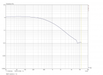
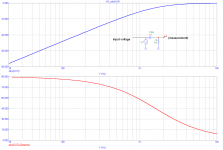
1st, let me comment that 100nF + 1k makes HF filter, F(-3dB) = 1591Hz. At 1kHz, we have -5.5dB amplitude roll off. The capacitor is substantially loaded by 1k resistor - this would never happen if the cap was used as a coupling cap.
I am attaching 3 measurements.
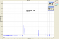
1) system distortion into 1k load. Input voltage 0.635Vrms.
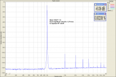
2) Same voltage, 100nF + 1k load.
3) 100nF + 1k, input voltage raised to get 0.635Vrms output voltage.
At 1kHz, almost 50% of the input voltage remains across 100nF capacitor. Capacitor and 1k resistor create voltage divider at 1kHz. Nevertheless, the 100nF mylar capacitor raised the system distortion no more than 0.001%.
Attachments

Last edited:
if the cap plates move under electrical signal then you can measure the C modulation as distortion, simple THD even - no problem
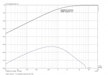
Would be nice to have THD vs frequency for a 10000uF lytic.
Would be nice to have THD vs frequency for a 10000uF lytic.
First please exactly define conditions of measurements. Let's not fight with windmills.
First please exactly define conditions of measurements. Let's not fight with windmills.
I would propose comparison
1) signal generator (amp) - directly coupled with 8 Ohms resistive load, THD vs F
2) signal generator - 10000uF lytic - 8 Ohms resistive load, THD vs F
Then one should plot [ THD(2) - THD(1)] vs F
I expect that the last curve will have some bumps at definite F
I have just tried a Panasonic Mylar 100nF capacitor.
1) system distortion into 1k load. Input voltage 0.635Vrms.
2) Same voltage, 100nF + 1k load.
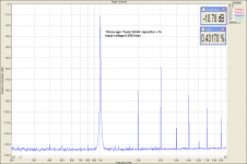
Same measurement as (2), for a 'stone age' (1975 plus minus) ceramic capacitor. We can see huge distortion, into 1k.
Attachments
I am just reading this :Burkhard Vogel: How to Gain Gain (Buch) – jpc
Over 800 pages about tubes in audio.
It is just sitting in my bookshelf next to his The Sound Of Silence. Mandatory reading if you are in low noise (pre)amplifiers!
Jan
Ahhh the capacitor merry go round, we know that certain types of ceramic caps are not suitable for certain circuit positions in audio circuits (not all are as bad John), but at least when showing measurements could we provide the class of ceramic dielectric, as there are big differences between class 1 and class 2.
As to 5U dielectrics only the cheapest of the cheep products use this sort of cap, most would use at least 7R or better, and in really critical decoupling situations or for coupling (RF) a class 1 COG dielectric. Comparisons of the different ceramic dielectrics would be nice instead of the standard audio practice of just lumping them as junk....they do have a role to play especially in digital audio.
As to 5U dielectrics only the cheapest of the cheep products use this sort of cap, most would use at least 7R or better, and in really critical decoupling situations or for coupling (RF) a class 1 COG dielectric. Comparisons of the different ceramic dielectrics would be nice instead of the standard audio practice of just lumping them as junk....they do have a role to play especially in digital audio.
All this info may be easily read from datasheet non-linearity charts. The purpose of plots was different - to show that mylar would make some distortion only when heavily loaded. 100nF mylar loaded with 100k will make no distortion. And no one would use 100nF X7R ceramic as a coupling cap.
It is just sitting in my bookshelf next to his The Sound Of Silence. Mandatory reading if you are in low noise (pre)amplifiers!
Jan
‘Low noise’ as far as defined by the theoretical circuit.
What's the point?
The way we implement a ‘low noise’ theoretical circuit may be THE decisive factor in the final measured noise of the built circuit, making me indifferent to the appeal of a theoretically low noise circuit.
Apart from PSU lines noise, ground loops and return current path most crucial issues, any single component of a circuit be it resistor, capacitor, inductor, semiconductor, PC trace, wire lead, is potentially a receiving small antenna.
It does act as a voltage generator with V=E0*l where E0 is the intensity of the field to which the component is immersed into and l is it’s physical length.
This formula holds linearly for l<L/10 (L wavelength of field components) and the efficiency of the generator will depend on the balance of impedances and component orientation.
Each such component is also a small transmitting antenna (current through the component is the new factor), making things much more complicated.
George
I believe Self has some info on electrolytic's distortion - points out that output speaker DC blocking is fairly rare in SS today
and that in input and feedback DC blocking putting the fc an order below audio pretty much does the job - no dV across the cap = no distortion
and that in input and feedback DC blocking putting the fc an order below audio pretty much does the job - no dV across the cap = no distortion
The way we implement a ‘low noise’ theoretical circuit may be THE decisive factor in the final measured noise of the built circuit, making me indifferent to the appeal of a theoretically low noise circuit. George
Yes, of course. And knowing some theoretical background will help you find the best implementation! The shoulders of the giants are there, so why not stand on them?
")
Jan
and that in input and feedback DC blocking putting the fc an order below audio pretty much does the job - no dV across the cap = no distortion
Yes, low enough Fc and avoiding capacitors like Y5, Z5, X7 etc. would prevent additional coupling cap distortion. We can see it even in case of ceramics that distortion rapidly falls down when we are moving away from Fc.
Attachments
Last edited:
I have just tried a Panasonic Mylar 100nF capacitor.
1st, let me comment that 100nF + 1k makes HF filter, F(-3dB) = 1591Hz. At 1kHz, we have -5.5dB amplitude roll off. The capacitor is substantially loaded by 1k resistor - this would never happen if the cap was used as a coupling cap.
I am attaching 3 measurements.
1) system distortion into 1k load. Input voltage 0.635Vrms.
2) Same voltage, 100nF + 1k load.
3) 100nF + 1k, input voltage raised to get 0.635Vrms output voltage.
At 1kHz, almost 50% of the input voltage remains across 100nF capacitor. Capacitor and 1k resistor create voltage divider at 1kHz. Nevertheless, the 100nF mylar capacitor raised the system distortion no more than 0.001%.
Measurement 3) would say more if it could be compared to a baseline for system distortion at the elevated voltage level.
= measurement (1). Input means input teminals of C-R, input to measurement is across R. C and R make voltage divider.
However, I am not sure why to bother with 100nF distortion into 1kohm load. This would apply only for filters of some kind, not for coupling capacitors.
However, I am not sure why to bother with 100nF distortion into 1kohm load. This would apply only for filters of some kind, not for coupling capacitors.
Attachments
Last edited:
PMA, not convinced, you did raise the voltage for measurement 3, so it makes sense that equipment hash generator side goes up as well, hence my suggestion to also baseline for the raised voltage.
Anyhow, I use caps in filter applications, and 100nF loaded by 1KOhm is a bit heavy, but 2kOhm loads are quite normal. So, for me, it's relevant (but no cause for worries because I came to trust a good cap).
Anyhow, I use caps in filter applications, and 100nF loaded by 1KOhm is a bit heavy, but 2kOhm loads are quite normal. So, for me, it's relevant (but no cause for worries because I came to trust a good cap).
- Status
- Not open for further replies.
- Home
- Member Areas
- The Lounge
- John Curl's Blowtorch preamplifier part II