IPC-610-D "Acceptability of Electronic Assemblies" gives suitable recommendations in Table 4-1 for wires and as usual, the answer is "it depends".
IPC standards are based on mechanical failures. A very good reference even if it is rather expensive. Most of the commercial lead benders comply with the standard.
However electrical changes are at the threshold of measurement following their bend standards for solid leads. Haven't really worried about stranded or coax. I try to keep coax to 30 diameters.
On a good video system you can actually see the results of over bending cable.
I would like to get back to the design philosophy of audio equipment and what we have learned (and unlearned) over the decades.
At this time, I happen to be mostly designing phono stages. I want first to talk about the phono stage and what we found important over the decades.
In the '50's and '60's, a traditional type of topology was mostly used. This was composed of 2 voltage gain stages, sometimes with a follower at the output. All the RIAA EQ was put in the single feedback loop. This design can be fairly quiet, fairly low in distortion, and fairly high in output voltage.
The weaknesses of this type of phono stage was EQ interactions of the passive parts, making the actual response usually a bit compromised, and not enough output current to properly drive a low noise RIAA network, leading to TIM.
Still, this topology is still used today by many engineers, and it seems to work and measure OK, BUT is it the best approach?
An alternative way is the 2 gain block approach that is usually more complex in thru-path, but it can be more accurate in frequency response and seems to sound better.
This is the approach usually used by high end designers.
Last edited:
Thanks Pooge, I will look into what the 'advantages are to a two stage design in the patent.
I first was told of a two stage design by a fellow who owned a Citation A preamp (I think it was the A) back in the mid-70's when he compared the JC-2 to the Citation A. About the same time, Bascom King told me about a version. At first, since the JC-2 was so popular, and took so few stages, I thought it should be better. However, 1978, HK found that the Electrocompaniet phono stage had some real qualities, and it was 2 stage, like the original HK, so I built one for them. After listening to it, I was convinced that the 2 stage design was better. Later, I built the JC-80 with it, and ultimately the Vendetta. All three phono stages that I am making now, are two stage, each varying in complexity and features.
I first was told of a two stage design by a fellow who owned a Citation A preamp (I think it was the A) back in the mid-70's when he compared the JC-2 to the Citation A. About the same time, Bascom King told me about a version. At first, since the JC-2 was so popular, and took so few stages, I thought it should be better. However, 1978, HK found that the Electrocompaniet phono stage had some real qualities, and it was 2 stage, like the original HK, so I built one for them. After listening to it, I was convinced that the 2 stage design was better. Later, I built the JC-80 with it, and ultimately the Vendetta. All three phono stages that I am making now, are two stage, each varying in complexity and features.
Grodinsky's patent is a good teaching about the engineering tradeoffs. Borbely's phono stage, independently designed later, was remarkably similar. In fact, if Grodinsky had better patent claims, he could have covered what Borbely created. I ask Grodinsky why he unnecessarily narrowed his claims, and he sighed that he wasn't too happy about his patent attorney.
How about this circuit ?
http://www.diyaudio.com/forums/analogue-source/54658-all-jfet-open-loop-riaa-pre-amp.html
Patrick
http://www.diyaudio.com/forums/analogue-source/54658-all-jfet-open-loop-riaa-pre-amp.html
Patrick
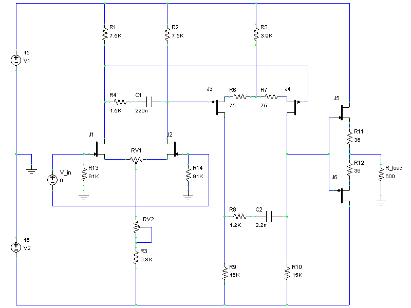
No it is Mr Evil's design, but I liked it a lot and did build a balanced version, some time ago.
The circuit
http://www.diyaudio.com/forums/atta...t-open-loop-riaa-pre-amp-preamp_schematic.png
is actually already fully balanced. We just need to add another JFET follower at the drain of J3.
In the one I built a few years ago, but I was too greedy and wanted 80dB gain in two stages (for MC). I also paralled 4 pairs for K170GR for the input stage, and ended up with too way much DC drift (volts). I did not add the servo right and ended up with instability.
But I think the drift can be brought under control by thermally coupling all JFETs, and also by reducing gain to 20 or 30dB per stage.
I do want to rebuild this agaon some time next year.
Of course it does not have the elegance of your complementary JFET input stage. But this is a very good circuit IMHO for its simplicity.
But maybe you would give us some pointers how to improve it futher ....
Patrick
I am not at home right now and next week.
When I am home, I shall dig the schematics and the layout up.
It is not the offset itself, because you can trim that, but the changes of offset with time that was causing the problem. I am pretty sure it was poor implementation on my side, and that thermal coupling all JFETs will make significant improvement.
Maybe I should have used K389/J109's instead.
")
Patrick
When I am home, I shall dig the schematics and the layout up.
It is not the offset itself, because you can trim that, but the changes of offset with time that was causing the problem. I am pretty sure it was poor implementation on my side, and that thermal coupling all JFETs will make significant improvement.
Maybe I should have used K389/J109's instead.
Patrick
I have never, to my knowledge, heard an amp with a servo control for DC offset. I don't see them mentioned much any more. I recall reading that there is a noise penalty?
I also haven't heard the optically variable resistors used in the Lightspeed Attenuator. They are reported to sound good:
http://www.diyaudio.com/forums/analog-line-level/80194-lightspeed-attenuator-new-passive-preamp.html#post924390
I was wondering if anyone had considered or tried using a DC offset servo to adjust a pot in the input stage, in the form of one of those optically responsive resistors, instead of injecting the offset control signal to the negative input.
I just fired up my new input stage with 16 total complementary input devices. It has 40dB open loop gain and almost no offset. I was lucky. Servo disconnected.
It would be interesting why you had so much offset. Maybe we should look at that first.
John,
Yada...yada,,yada...
Don't you think it is time to try something newish!
In my current amp design I use a thermal servo. The input devices are mounted around two vertically mounted 5 watt resistors. A National temperature sensor is used to set the base temperature rise, then the output offset is used to tweak the temperature differential. The offset is limited by the trim of the thermal feedback opamp.
If you want to get fancy you can use two integrating capacitors in the thermal feedback loop. One a low value for fast turn on and then a large one for very slow changes. Or you can use a trim for turn on and one large one.
Of course I am using bipolars, you might want to try a thermo-electric cooler.
Of course if you don't really want state of the art you can use a thermistor with a heater for the DC offset adjust, that technique has been around since the 40's. Crystal ovens are even older.
The gain stage will probably be current conveyors and they really need the thermal trick to keep their gains the same for best results.
I am at least a year away from finishing the design, so don't ask for a schematic.
ES
Yes, Simon, I am using tried and true techniques, as they work for me. I'm glad that you are going forward with new, 'crazy' ideas. It can be fun.
Looking at the offset problem with Evil's design is for a different reason than I might have. One problem is that there is no real reference to ground within the circuit. You can set it to 0, once, but any temperature or supply voltages will upset the setting. It is really a common mode offset, because it could be balanced out with an ideal transformer added to the output of the balanced version. With single ended, you would see it as just offset. That is why I use 2 different servos, one for differential offset, and one for common mode offset. I was fairly successful, without any initial adjustments, because I have a ground reference at the output, and the complementary design tends to track with temperature differences.
Looking at the offset problem with Evil's design is for a different reason than I might have. One problem is that there is no real reference to ground within the circuit. You can set it to 0, once, but any temperature or supply voltages will upset the setting. It is really a common mode offset, because it could be balanced out with an ideal transformer added to the output of the balanced version. With single ended, you would see it as just offset. That is why I use 2 different servos, one for differential offset, and one for common mode offset. I was fairly successful, without any initial adjustments, because I have a ground reference at the output, and the complementary design tends to track with temperature differences.
- Status
- Not open for further replies.
- Home
- Member Areas
- The Lounge
- John Curl's Blowtorch preamplifier part II