> Do you see another way to optimize it.
A few ideas from me :
1) replace R6 with a single LM329AD.
2) replace I1 with a degenerated 2SK246BL to 2.7mA.
3) replace V1 with 3x 3.3V lithium batteries, probably with caps in parallel
4) add a 2SK369V to each of Q1,3,4 as cascode, with the gates tied to the top of C1.
Especially (4) will equalise the dissipation of all 4 BJTs.
Patrick
scott what you think about the #44657 circuit ?
Do you see another way to optimize it.
I would like to find alternatives to lm134.
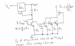
Now you are simply multiplying a floating current source up, sort of begs the question of why not setting up the LM134 for 8mA in the first place.
If you go back to a voltage reference and resistor but stand the reference up on a diode connected transistor you get pretty close. If you use a reference with very low supply current the current density coming and going is pretty close.
EDIT - LT6656 has only 850nA, so stick the diode connected transitor in the ground return of your first circuit and recompute values keeping the current densities all the same. At 8/3mA out of the reference the 850nA will be a trivial error far better than the matching of the discretes. Of course we might have an equivalent part.

Last edited:
>
4) add a 2SK369V to each of Q1,3,4 as cascode, with the gates tied to the top of C1.
Especially (4) will equalise the dissipation of all 4 BJTs.
Patrick
You could get away with 1 FET with BJT collectors tied. Did you get the gist of that last comment? I should have said take the circuit with 4 BJT's, replace I1 back to a resistor, take a series regulator with very low Isupply and put another diode connected BJT and 1.8k in its ground lead. Now the circuit forces 5V across the R (2.7mA) and all the Vbe's are compensated. I don't think 2.7mA vs 2.70085mA will be your limiting error.
Last edited:
On another point, has anyone ever looked at Vbe variation on parts pulled consecutively
off of tape and reel or equivalent. I suspect it is smaller than one might guess.
I have done this for Mosfets on tape, and the Vgs was generally a decent
match for adjacent parts, and then I periodically got a discontinuity,
presumably when whatever was picking the die had started a new row
on the wafer.
So you might still want to check the parts.
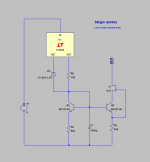
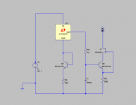
This is what I going to use,
the current variation between 10º and 40º Celsius is only 600nA, and that is less than I was needing.
I may or may not use J1.
To change the current out, alter R5 with ( Iout=1.25/R5 ).
Thanks for all the sugestions
PS: Q1 and Q2 are dual version.
.
the current variation between 10º and 40º Celsius is only 600nA, and that is less than I was needing.
I may or may not use J1.
To change the current out, alter R5 with ( Iout=1.25/R5 ).
Thanks for all the sugestions
PS: Q1 and Q2 are dual version.
.
Attachments
Last edited:
With J1(2n4393) the current variation is only 300nA (10º to 40º).
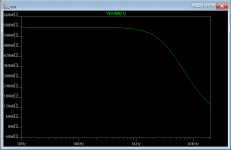
first image is output impedance
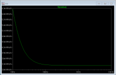
second image is noise in a 350R output resistor.
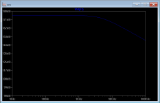
third image is PSRR.
first image is output impedance
second image is noise in a 350R output resistor.
third image is PSRR.
Attachments
Last edited:
Not if your interest is, say, USB audio
Jan
Hi Jan,
No, my main interest here in this thread is to learn as much as I 'curl' and can about the "purest and perfectest blowtorch preamp" in the whole world!
Without a preamp there wouldn't be Music.
And right beside a pair of loudspeakers, in a certain dedicated room, the preamp is the most ecclesiastical (essential institutional) audio component around;
there is simply no two mechanical ways around it!
Last edited:
Scott,
Why is it important that the series reg has low I_supply ?
So that the current can get through the diode connected transistor ?
How low is low ? <<1mA ?
Patrick
To keep all legs at the same current, I guess I need to provide a schematic.
You could get away with 1 FET with BJT collectors tied. Did you get the gist of that last comment? I should have said take the circuit with 4 BJT's, replace I1 back to a resistor, take a series regulator with very low Isupply and put another diode connected BJT and 1.8k in its ground lead. Now the circuit forces 5V across the R (2.7mA) and all the Vbe's are compensated. I don't think 2.7mA vs 2.70085mA will be your limiting error.
scott, can not understand sorry.
I guess today Im slow, only with a drawing
I have done this for Mosfets on tape, and the Vgs was generally a decent
match for adjacent parts, and then I periodically got a discontinuity,
presumably when whatever was picking the die had started a new row
on the wafer.
So you might still want to check the parts.
Excellent call.
I've had problems with parts which occurred every 4th die, and the manu identified it as a primary mask defect. Either they stepped a 1 by 4 mask over the entire wafer, or they stepped it to make the final mask.
But that was back in the early 80's, when we had to be wary of the raptors..
jn
drawing
thanks, Dimitri.I think the circuit will not work , but give me an idea.
Last edited:
I think the circuit will not work , but give me an idea.
Yes I mis-spoke the reference should just be on top of the diode connected transistor. Also these circuits can have considerable beta errors which can be fixed first order if the betas sort of match. Sorry Dimitri you drew exactly what I said, I just had the wrong picture in my head.
Regulators with <1uA standing current are available, that is far better than one could ever count on matching base currents at 8mA collector current. This circuit wraps up nicely also as floating current source, with care a 2.5V reference could be used and the compliance could be 5V or so with no real penalties. Current is then 4X rather than 3X.
Attachments
Last edited:
- Status
- Not open for further replies.
- Home
- Member Areas
- The Lounge
- John Curl's Blowtorch preamplifier part II