Now I see the source of confusion. The Equivalent Series Inductance (ESL) of most electrolytic capacitors is measured at .5 Volts AC RMS 100 or 120 Hz.
Bad assumption. Start with that and nothing else will be correct. ESL is commonly measured by plotting Z vs f and seeing the resonant frequency. You check it by extrapolating the upward part of the curve to the f axis. That's how the plots in Jones and my own measurements are generated.
Yes, if you lay things out badly or measure poorly, you'll see worse numbers.
Did-you mean the Blowtorch thread has to die ?Stop trolling, guys ...
Last edited:
Last call on the music thing. When I first got into the CD music scene it was "shock" after "shock" buying favourite albums, and the sound being so different from how I remembered it. But, the realisation and understanding came in quite some time ago that at least a major part of the answer was that I had so much more access to what was the "real" recording, being able to hear into the studio so much further. Recordings which I had originally thought spectacular seemed very manipulated, and others which had been relatively straighforward, or cluttered, became marvellous soundscapes.
Got over that years ago, automatically assume that a "familiar" recording will in fact be a whole new experience, it's a journey of discovery every time ...")
Frank
Got over that years ago, automatically assume that a "familiar" recording will in fact be a whole new experience, it's a journey of discovery every time ...
Frank
Nearly every time I listen to an expensive, or pretentious system I can hear plenty of "evil", and it has nothing to with -200dB levels of 7th harmonics. To pull a car analogy, it has to do with trying to drive a Ferrari with flat tyres; there are major problems with the setup as a whole, and minor inconsistencies are blown away in the face of the "big" issues ...While i'm not able to hear any obvious difference in my system between my preamp (Ic based) and a short wire, i do not ask myself questions about any evils.
Frank
I totally agree with both of your messages, fas42.
About recording and mixing, it was the poor quality of the audio chain (including studio stuff) witch brought us to manipulate the sounds so much. With digital, and even with the same 'production climax' goal, i would be a lot less intrusive, today. As the pleasure can be in the instrument itself, if it is good sounding enough and well played.
About so called 'high end' systems, i often run away very fast with a grimace from the demonstration rooms, sometimes very impressive, with no connection to the reality...
Bad assumption. Start with that and nothing else will be correct. ESL is commonly measured by plotting Z vs f and seeing the resonant frequency. You check it by extrapolating the upward part of the curve to the f axis. That's how the plots in Jones and my own measurements are generated.
Yes, if you lay things out badly or measure poorly, you'll see worse numbers.
This is quit true.
In addition: For smaller values which are harder to measure the Ls and esr, you can charge the cap to 1-5vdc and then short the leads together (with shortest distance/lead length possible). Dont do this with a large value cap - the currents will be extream and can heat the cap and damage it. Then pick up the current signal flowing in the Cap leads via inductive probe. You will see a ringing waveform with a decay. The freq of the ringing is the natural resonance freq of the cap with that amount of lead length and internal Ls. The oscillatory decay rate depends on the bulk resistance and the esr. Knowing the value of C and freq of ringing you can calculate the Ls.
Better is to do same test with cap on (empty) pcb with trace and wires attached.. obviously the resonance in-circuit will be lower and total Rs (including esr) also higher and that is all that really counts.... performance in-circuit... not what a cap does all by itself. [a superior cap measured out of circuit can become the worst cap with added Ls and Rs of circuitry to/from the cap.]
-RNMarsh
Last edited:
we do have an active thead showing PS C Z measurements http://www.diyaudio.com/forums/powe...work-analyser-measurements-4.html#post3331935
JC, I'm not sure you are competent to do even simple designs with OPAs.No, PMA, but I like the open-loop bandwidth and the subjective sound quality, and it uses a jfet input, which is the best that I can get from IC's.
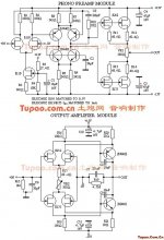
- In JC2 Mk1, you use an excellent OPA (AD797) in an application which is completely unsuited to it (MM & MC preamp).
- Your naive circuit introduces more than 10dB extra noise.
- You ignore the datasheet recommendations on decoupling, guaranteeing the distortion is nowhere near its potential and the device probably unstable.
- When the product is rightly criticised by the reviewers, you blame the OPA when the faults are due to your poor design & choices.
- It is likely you didn't pick up these faults cos you were unable or unwilling to do even do the most basic measurements on the final product.
we do have an active thead showing PS C Z measurements http://www.diyaudio.com/forums/powe...work-analyser-measurements-4.html#post3331935
Network analyzer always works of course for measuring Z. I have a couple of them plus A-P and SRS precison LCR bridge --- but -->
If the cap self resonance is beyond the range of your equipment my alternate approach can be used and checked by anyone with a scope.
More importantly, you can also see affects of heating to high current transients. And, compare the effect on current pulse amplitude thru the real device at real current levels... (tens of amperes) not easily done with a low voltage/low current network analyzer. Thx-RNMarsh
Last edited:
May-be more transparent than the original signal ?I wonder if one were to chain 10 Blowtorchs whether it would still be considered transparent ...
(Sorry i couldn't resist
Examples:
right ...
jfets as inputs help with rf demodulation
issues as well as having built in source degeneration
(compared to a bipolar in the same position)
assuming the drain to be a voltage controlled
current source, and a bipolar as a current controlled
current source ..... viola
- Status
- Not open for further replies.
- Home
- Member Areas
- The Lounge
- John Curl's Blowtorch preamplifier part II