Worth repeating, Nelson didn't have to work too hard to find pathological combinations.
"However, the best sound cables were not necessarily electrically the best because several amplifiers preferred the highest resistance cable. In one case, I had to use 24 gauge cable to prevent tripping the amplifier's protection circuitry."
"However, the best sound cables were not necessarily electrically the best because several amplifiers preferred the highest resistance cable. In one case, I had to use 24 gauge cable to prevent tripping the amplifier's protection circuitry."
Exposed to what ?Sorry Nelson, for exposing you to all this ---. ,-)
No bullsh..., in this paper, no snake oil. Just well known and incontestable facts.
And a demonstration of the utility of my fight for compensating impedances of enclosures to get a flat curve.
Last edited:
Sorry Nelson, for exposing you to all this ---. ,-)
To what? Is it an inconvienient fact that somewhere out there probably more than once an amp got slagged or cables "removed the last veil" only because the amp was made to oscillate or made stable by the cable/speaker combination.
If I am following this discussion of speaker cables correctly then I think that this is what I am taking from it. We first off would need to know both the source impedance and the load impedance of the loudspeaker to understand the interaction here. If a speaker has a properly designed Zobel network I would imagine that this would eliminate most problems and we could then look at the load impedance as being a fairly smooth impedance without becoming reactive. Now what happens if we do not know the source impedance of a power amplifier?
To people who will parse his paper.
It serves no useful purpose to publish then disregard any questions or comments regarding technical content. Nor to whine about it. Nelson does neither, others should follow his footsteps.
Having significant experience in high current slew rate and extremely low impedance circuitry beyond the reach of most, I can certainly come up with questions yet to be asked, on things yet to be considered in directions never thought of. edit(being crazy certainly helps me in this regard)😉
We all bring different expertise to the table. That is what a discussion is all about.
Sure, on occasion we all go down the wrong path. It wouldn't be fun any other way.
jn
Last edited:
Mr Curl. Re: #30705. Thanks for the tip. Could you quote a "ball park" figure for the value of the coil pls?
Thanks. Jonathan
Thanks. Jonathan
My guess is the cable is doing this:
Ayrton-Perry winding - Wikipedia, the free encyclopedia
(The double orthogonal spiral cable mentioned by Dick Marsh that is.)
wrinkle
Ayrton-Perry winding - Wikipedia, the free encyclopedia
(The double orthogonal spiral cable mentioned by Dick Marsh that is.)
wrinkle
Last edited:
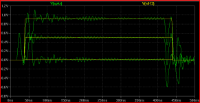
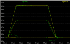
again with the lumped TL sim - added 84 Ohm spice lossless tline element, trimmed the delay param to 28 ns for OK match with my previous sim 12' Pass 18 awg zip cord speaker cable model
stepped termination R = 1, 84 and 1k Ohm - plotted Vsoucre V/I = impedance at driving end
sure looks like the lumped model shows some transmission line characteristics - to well over 10 MHz
the lumped model pulse waveform has some major features differing with short, open end, but the terminated rise time is delayed by the the same 28 ns that makes the Z plot match (pulse start delayed 10ns)
won't show multimode behavior - but do we need it for loudspeaker cable
I must say I'm not at all sure about where the 28 ns delay number comes from - I would have guessed 12' of not exotic Z cable delay ~18 ns I suppose I could look for the equations...
Attachments

Last edited:
Two transmission lines with the same impedance, attenuation and time delay will behave the same, whatever their physical length. Differences will only emerge at high frequencies where the plain TEM mode is no longer dominant.
A lumped approximation to a line will become a better approximation at lower frequencies, or at a fixed frequency with more lumped sections. Putting a square wave through a lumped line may show differences if the rise time is short enough to probe the frequency region where the lumped approximation is no longer good.
A lumped approximation to a line will become a better approximation at lower frequencies, or at a fixed frequency with more lumped sections. Putting a square wave through a lumped line may show differences if the rise time is short enough to probe the frequency region where the lumped approximation is no longer good.
Two transmission lines with the same impedance, attenuation and time delay will behave the same, whatever their physical length. Differences will only emerge at high frequencies where the plain TEM mode is no longer dominant.
Nice theory. The real world begs to differ.
The ear hears a difference....Ah, science!
Science...where observation is king. Why, throw away observation, and you'd be left with unchanging dogma.
So the ear hears a difference. Then, we move forward from that observation....
...on a side, and sales methods to convince customers they hear a difference, on the other. ;-)well there are scientific standards for demonstrating that the ear is hearing the difference...
What is the bottom green trace ? The error level ?
Last edited:
Thanks for this Pavel. I'll file it under the caveats for LM4562.opamp dc offset.pdf
To me, the part does not meet specs. It is unable to withstand +/-10V 200kHz square at the input for gain +1. And it was RC filtered. Please read more carefully. Once again the test. It was tested by sine OR by square. Not both together.
It's an extreme case of PIM as the square wave is producing huge distortion at 0Hz.
If you have an evil NJM4562 handy, it would be nice to see if this much more primitive topology has this behaviour.
There are always good reasons for the survival of Jurassic circuits, some of which are quite subtle and incomprehensible to pseudo gurus who pontificate on the latest fashionable test/distortion/component etc. Time is probably the most critical judge.
I should add that LM4562 is a very good OPA for applications that avoid its problems. As is NJM4562 when low Ib is not essential.
OPA2134 has been unfairly damned with faint praise by Self and others. But in complex products with loadsa OPAs & frequency shaping stuff like a mixer, it often outperforms the new uber OPAs ... even in their forte which is pp zillion THD.
My guess is that it is less fussy about earthing & decoupling than these highly strung racehorses ... though it still pays to pay scrupulous attention to earthing & decoupling even with cheapo OPAs. Many Golden Pinnae products with $$$ OPAs don't .. which is why they can bomb out compared to good cheapo stuff.
Alas, if you are trying not to degrade the S/N of a 24b system, the resistor you are allowed is often so small as to be useless. Comparing OPA627 and AD797 datasheets is instructive. This is more of a problem on the recording side than on playback.jneutron said:The least ya coulda done was put a resistor in the feedback path so the device couldn't shoot itself in the foot.
I'll admit trying for 20b performance on playback is probably a better REAL life target if it facilitates solving more audible problems
It was the 1st opamp that has always gone. The input to 2nd opamp (with gain 2x) was divided 2x. The 2nd opamp served only to monitor output of 1st opamp and to drive RC filter (R1,C1) to get DVM DC reading.
Nice work Pavel, correlates very well with what Ed Simon noticed and what my ears have told me 🙂 Given what Walt Jung found in his regs, I surmise that the AD797 would also fare badly in this test?
Last edited:
Some of the complaints here about the EXTREME cost of the CTC Blowtorch got me to think about WHY we made such a costly product, even for ourselves, and what would would, more-or-less work, if we were willing to compromise on convenience.
Before we started even building the CTC Blowtorch, I had a Levinson JC-2 and a JC-80 in my closet, along with the Parasound HCA 1100,1500 and 2000.
Yet, I did not put any of these preamps in my system. So what did I use?
I used a GOOD dual wirewound pot that I connected between a Vendetta Research phono stage and the power amp, or I plugged in a vacuum tube FM tuner into the wirewound pot, instead. Why? Well, it sounded 'cleanest' this way, rather than ANY of my other designs. In truth, I originally doubted that the CTC Blowtorch would meet or beat this combination. Thank goodness, I was wrong.
Now the reasons WHY this is so, is what this thread is all about, at least from my point-of-view.
This wipes away any possibility that a typical IC will do the job, as ALL the preamps listed above are discrete Class A preamp designs, and THEY did not make the grade.
It is important to look beyond 'a simple gain stage' to get optimum listening performance. This has been my experience and I will stick with it. .
PMA..
During the square wave test the device started increasing it's DC offset voltage, 5.3 volts DC at 200Khz.
I'd be worried about toasting the input pair at that drive level. The DUT is clearly no longer able to keep the negative input node close to the positive input. So I'd suspect sending one of the E/B junctions into avalanche.
jn
Apologies Pavel - I read your 20 V pk-pk as 20 V pk.
I think Jneutron has probably nailed it.
The spec sheet on this device does not include a simplifed circuit diagram, or the max differential input voltage or current. Given the low typical bias current of 10nA, the input devices are probably quite fragile, and may even have back to back protection diodes or transistors across the inputs.
In any event, I would not normally envisage this device being driven at these levels - but clearly if there is the oportunity for inputs at these levels, then some form of protection is needed. Onwe idea might be to connected to low capacitance diodes back to back across the inputs (you can get devices with 1-2pF capacitance).
I will give some feedback on the TI website - hopefully they can provide an explanation.
- Status
- Not open for further replies.
- Home
- Member Areas
- The Lounge
- John Curl's Blowtorch preamplifier part II