I might clarify what I mean by 'noise gain' or whatever it is called formally.
The first estimated example of this, I learned from a classroom handout of the UA741 op amp that had been analyzed by the best SPICE emulation at the time. It was shown that the bipolar active loads actually ADDED noise to the op amp, because they were not degenerated enough to kill their noise gain. This was a revelation to me, in 1971. I would have never thought it would be important, until it was discussed in class.
You see, we normally think of the input device(s) as the primary noise generator, because we normally use a resistive load. However, when we use an active load, then the load itself can amplify its own self noise, and sometimes overwhelm the input noise. The easiest solution is to add emitter resistors in order to reduce the intrinsic gain of the active load. However, too much emitter resistance will cause voltage drop problems that could effect the common mode range, or the maximum output swing of the circuit. This is where 'finesse' is required, to keep the potential problems almost negligible.
Interesting. Similar results were found by Ovidiu Popa in his Linear Audio Vol 1 article. He looked at the noise tradeoff in a low noise input stage with a CCS load with the usual FET + source resistor. He found that with a CCS you got (of course) much higher stage gain but also much higher stage noise because the CCS had a 'noise gain' of itself. So the S/N didn't change whether you used the CCS or - get this - a resistor of the value used to set the CCS current. Another nice example of noise gain indeed.
jan
Also, since it's your design, have you ever assigned a name to the circuit (as in a Curl "curl")? I've read that Grey Rollins asked you for a circuit name several years ago.
http://www.diyaudio.com/forums/soli...gle-ended-folded-cascode-vas.html#post1663009
(Post 13)
That active loads amplify their own noise has been discussed in
the Gray&Maier text book on analog chip design some 30 or 40
years ago, at length.
(Meier sp??)
And noise gain is a well-defined terminus technicus in feedback theory,
it should not be abused here.
regards, Gerhard
the Gray&Maier text book on analog chip design some 30 or 40
years ago, at length.
(Meier sp??)
And noise gain is a well-defined terminus technicus in feedback theory,
it should not be abused here.
regards, Gerhard
PMA,
What your simulator shows when you add emitter degeneration resistors to the current mirrors? I am very curious...
Best,
As low value as possible in the output stage emitters. In simulation, the standing current is stable with temperature. It would need to build a real sample.
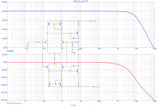
Noise simulation says 2.4nV/rtHz ref input.
Last edited:
That active loads amplify their own noise has been discussed in the Gray&Maier text book on analog chip design some 30 or 40
years ago, at length. (Meier sp??)
[snip]
Yes, it's very hard these days to find something that is not really 50+ years old, including live audio engineers ;-)
And noise gain is a well-defined terminus technicus in feedback theory, it should not be abused here.
regards, Gerhard
Agree again. I should have put it between quotes to avoid sloppy use. My bad (and John's!
") ).
).jan
Thanks Gerhard. In fact, it was Dr. R.G. Meyer's class at UC Berkeley in 1971 that I learned this. I was very impressed at the time. I will look at my copy of G&M for the reference pages. Dr. Meyer, who is slightly younger than me, still taught me a great deal in these classes I attended more than 40 years ago.
Groner also has a discussion of current mirror noise in his critical review of one of Self's books.
If one thinks of it qualitatively, a unballasted current mirror is an example of a "translinear" circuit, where the nonlinearity of the diode-connected transistor predistorts the input signal to the other device. A diode-connected transistor is a shunt-feedback amplifier, and has the noise of the transistor, the base-spreading resistance thermal noise and the "half-thermal" of the equivalent emitter resistance. These r.m.s.-add to determine the voltage at the collector-base connection.
Now this is the input to the output device, which converts it to a current at the collector in accordance with its transconductance. And this device also has its own noise. Overall the two contributions are about equal.
The effect of such a current mirror on the overall differential stage noise is to raise the net noise current at the output of the stage by 3dB, for an unballasted differential pair. If, otoh, the pair has emitter degeneration, the degradation is correspondingly higher. And Samuel points out that sometimes Self errs a bit on too-low ballasting in his current mirrors for overall "blameless" noise performance.
Now, as JC has mentioned, one does not simply make the mirror resistors indefinitely large as this can cut into the available voltage swing. As well, resistors slow the mirror down, so there is also a tradeoff with overall bandwidth. In the typical current-feedback amplifiers the schematics at least usually show no ballasting (they also show the use of Wilson 3-device mirrors, which have their own tradeoffs).
Brad
If you really want an example of noise problems due to active loading, analyze a UA740 sometime (no that is not a typo). '-)
Other examples of the limitations of unballasted current mirrors are the ancient operational transconductance amplifiers, the LM13700 or NE5517 (National Semi or Philips/NXP etc.). Here the input differential stage has each collector provide input to Wilson mirrors off of the positive rail, and one of the mirror outputs gets mirrored again off of the negative rail, with the output finally being the connection of the upper and lower mirrors (hence a relatively high impedance or "current" output). The mirror noise dominates the overall noise performance.
It is possible to get some fairly decent performance out of the parts, but one has to work quite hard. Self dismisses the parts in his Small Signal Audio Design, having been frustrated trying to use the application suggestions, which indeed do not work very well. However, with differential drive and using the on-chip translinearizing diode-connected transistors, you can get fairly reasonable distortion performance. And by varying both the standing bias current in these diodes as well as the tail current for the input pair, you can get quite a decent range of variable gain.
Brad, you know this?
Hadn't seen that! Thanks!
... or knit your own using those CA3080 and CA3046 arrays. Build my first OTA with those!
jan
CA3080 was an early OTA. CA3086 was the less-specified transistor array, -3046 the one with a few more guarateed specs, and CA3045 the ones in beautiful* ceramic and gold packages. They had good F sub t, moderate beta, and abundant popcorn noise. A funny story: my father was aware that his switching system modules didn't look modern enough. So he decided they needed to have at least one integrated circuit. But his chief designer merely ported the existing discrete transistor design into one using the 3086, with a 2N2222 used for the actual relay driver. Life went on.
SGS (now STMicro) did a look-alike version of the 3046, and their datasheet was in essence a carbon copy of the RCA one. However, they used a drastically different process with a terrific improvement in beta and reduction in noise. I discovered this when I got some samples, and was delighted. However shortly after that they discontinued it.
Brad
*I don't get out much.
Brad Plunkett was also a fan of those arrays, and when we compared notes we found that we'd done similar things with them, including an on-chip heater-stabilized differential pair. I did a bandgap reference once, although it didn't work very well. I used one in the last OEM automotive thing I did for Harman as part of a current-steering limiter cell, but the design was scrapped when I resigned to become a consultant, and they found that the input stage (which used a topology exploiting the low swing of the ground leg of the input in a single transistor-based differential amplifier which required no matched resistors and did >60dB conducted CM noise rejection), was susceptible to high frequency noise when used in the dreaded "parallel-wire" test dictated by Ford. David McCorkle discarded the whole thing and did a conventional diffamp. Probably a good input common-mode choke would have worked, but I can hardly blame him for following the path of expediency.
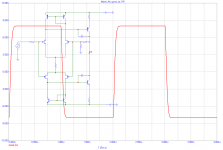
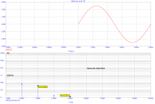
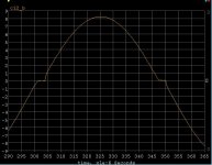
Some simulation results.
What about offsets? There is no voltage response to the output to common mode current in the output devices, i.e. as long as they are the same they could be almost anything.
EDIT - With 20mV delta Vp on the FETs circuit has no equilibrium for the two high gain nodes at zero crossing. At 5mV delta Vp the circuit finds equilibrium but the quiescient current of the output stage goes down to .6 mA from 3mA and the THD is not very good.
Attachments
Last edited:
but the quiescient current of the output stage goes down to .6 mA from 3mA and the THD is not very good.
The quiescent current of the output stage is about 15mA in my circuit.
The quiescent current of the output stage is about 15mA in my circuit.
This circuit perpetuates the same design error as in the famous Randy Slone's book, fig. 11.4, discussed in extenso here: http://www.diyaudio.com/forums/solid-state/16796-unstable-vas-current-amp-slone-book.html
Essentially the output stage bias current is undefined; not only component dispersion, but also temperature variations will flip the bias current from zero to God knows where.
I doesn't matter if an output servo is added, the output stage bias current is not well defined even if the output is kept (by the servo) at zero volt.
Such "designs" work very well in simulators (perfectly matched components, etc...) but never work properly on the bench, or at least can't be reproduced with any degree of certainty.
Last edited:
- Status
- Not open for further replies.
- Home
- Member Areas
- The Lounge
- John Curl's Blowtorch preamplifier part II