Scott,
You know me too well.
V=q/C CV=q C*dv/dt + V*dc/dt = dq/dt = i
The basic capacitor equations. Most people ignore dc/dt even thought there is always some force from the plate charge attraction. That is one source of distortion in real capacitors.
But as the question was for a theoretical version we can ignore dc/dt.
Instead we can recognize all circuits have some internal resistance.
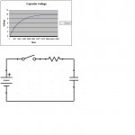
That brings into play the classic unit impulse applied to a capacitor through a resistor. The charging current is initially determined by the charging current or V/R. As the capacitor charges then V across the resistor drops and the charging current drops. All basic stuff from field theory.
As in audio circuits we do have a voltage source with an internal resistance feeding a capacitor which also feeds into a load resistance there will be some of the same exponential effect.
Now Scott, I know you don't worry about the small things, but here is where it gets interesting, the common calculation for low frequency cut-off is 1/(2*pi*R*C)=F. At that point the distortion from the current limited exponential curve may be greater than the rest of a modern amplifier circuit! So pain in the a... oh I mean high end audiophile designers have claimed to have heard this distortion. Their solution is to use high impedance loads on all capacitor coupled circuits!
Now just to make things interesting the dc/dt effect (or maybe it is just the bad capacitor distortions I have measured at higher frequencies) tends to be less in low impedance circuits!
So yes it is more anecdotal evidence of at what level distortion can be detected.
The issue is that a good designer can calculate the nonlinear distortion cause by limited current in capacitor coupled circuits to be sure it is well below other less manageable sources!
ES
You know me too well.
V=q/C CV=q C*dv/dt + V*dc/dt = dq/dt = i
The basic capacitor equations. Most people ignore dc/dt even thought there is always some force from the plate charge attraction. That is one source of distortion in real capacitors.
But as the question was for a theoretical version we can ignore dc/dt.
Instead we can recognize all circuits have some internal resistance.
That brings into play the classic unit impulse applied to a capacitor through a resistor. The charging current is initially determined by the charging current or V/R. As the capacitor charges then V across the resistor drops and the charging current drops. All basic stuff from field theory.
As in audio circuits we do have a voltage source with an internal resistance feeding a capacitor which also feeds into a load resistance there will be some of the same exponential effect.
Now Scott, I know you don't worry about the small things, but here is where it gets interesting, the common calculation for low frequency cut-off is 1/(2*pi*R*C)=F. At that point the distortion from the current limited exponential curve may be greater than the rest of a modern amplifier circuit! So pain in the a... oh I mean high end audiophile designers have claimed to have heard this distortion. Their solution is to use high impedance loads on all capacitor coupled circuits!
Now just to make things interesting the dc/dt effect (or maybe it is just the bad capacitor distortions I have measured at higher frequencies) tends to be less in low impedance circuits!
So yes it is more anecdotal evidence of at what level distortion can be detected.
The issue is that a good designer can calculate the nonlinear distortion cause by limited current in capacitor coupled circuits to be sure it is well below other less manageable sources!
ES
Attachments
Except, of course, when the circuit requires a coupling capacitor (as many do).john curl said:No coupling capacitor is the best coupling capacitor. '-)
What distortion? What current limit is this? An RC circuit has an exponential time domain response, and a first-order filter frequency domain response. Two different ways of looking at the same thing.simon7000 said:the distortion from the current limited exponential curve
Last edited:
Boron nitride.
That's what I was thinking. I never knew that packages were made with it though. I've used aluminum nitride, but never heard of boron nitride based ceramic packages..
Guess the old adage is incorrect, I larned sumptin..even though I'm an old guy.
Cheers, jn
What distortion? What current limit is this? An RC circuit has an exponential time domain response, and a first-order filter frequency domain response. Two different ways of looking at the same thing.
You normally seem to come to the party albeit often a bit late. So how do you get any voltage without a source resistance? How does current pass through a capacitor?
Sorry, I don't understand the point you are making. You appear to be claiming that the exponential time domain response of a CR circuit somehow creates distortion. Either I have seriously misunderstood you, or you are talking nonsense.
Well let us see if we can find points of agreement and build on that.
There is some source resistance in all real voltage sources.
The voltage across a capacitor governs the charge; V=q/C.
dq/dt = i
ES
That's what I was thinking. I never knew that packages were made with it though. I've used aluminum nitride, but never heard of boron nitride based ceramic packages..
Guess the old adage is incorrect, I larned sumptin..even though I'm an old guy.
Cheers, jn
I love to larn.
The story about lossy dielectrics with respect to charge amps is not without some human drama. At risk of repetition (I think I touched on it somewhere recently, maybe not in here): Landis et al. at Lawrence Berkeley decided that the high-meg feedback resistor in charge preamps was a big bother, so decided to pursue a strategy for its removal. Given that the x-ray spectrometer detectors they were using had a negative output charge signal, they needed some positive charge to offset this to keep the preamp output from banging into the rail.
So they decided to use the drain-gate junction of the JFET as a photodiode. In order to do so they removed the JFET from the case, still sitting on top of the gate lead (these were 4416s and quite small). They published their results, ecstatic at having achieved a large reduction in charge noise --- IIRC about 10 r.m.s electronic charges for their processing bandwidth. They couldn't quite explain why things had improved that much, but they thought it was that nasty feedback resistor being gone.
Kern and Mackenzie conjectured that the by-far-more-important effect was the elimination of the borosilicate glass, and proceeded to do a conventional preamp with a feedback resistor, but with the JFETs packaged in low-loss headers. They got comparable results for noise. But by then the light reset bandwagon was rolling, and few noticed K & M, and virtually all thought photonic reset was cool. GE (?) in the UK started making FETs with translucent packages...
Bell Labs had a nasty habit in those days of correcting people a lot
")
Pulsed reset schemes are still advantageous for high count rates and particularly when the count rate is variable, so the schemes are still of value.
Brad
You appear to be claiming that the exponential time domain response of a CR circuit somehow creates distortion. Either I have seriously misunderstood you, or you are talking nonsense.
To help with explanation, when we say distortion without adjective, we mean non-linear distortion, i.e. new harmonic components are created. The RC circuit cannot create new harmonic components, it can only introduce linear distortion, i.e. change in time and frequency response (change of amplitude of harmonic components existing in the original signal) without creating new harmonic components.
Last edited:
Scott,
You know me too well.
Now Scott, I know you don't worry about the small things, but here is where it gets interesting, the common calculation for low frequency cut-off is 1/(2*pi*R*C)=F. At that point the distortion from the current limited exponential curve may be greater than the rest of a modern amplifier circuit! So pain in the a... oh I mean high end audiophile designers have claimed to have heard this distortion. Their solution is to use high impedance loads on all capacitor coupled circuits!
ES
Ed your reasoning is way off here, a sine wave applied at cuttoff will experience no THD. Without an explicit dielectric problem this is not a source of any distortion not even at your usual levels.
BTW do the force between plates with a nice 0dB line level and you will not see much dC/dt. If you read Samuel Groners stuff there are some fairly mundane caps at <-140-150dB.
Ed your reasoning is way off here, a sine wave applied at cuttoff will experience no THD.
.... and it has infinite spectrum, when cut instantly, even at zero crossing.
.... and it has infinite spectrum, when cut instantly, even at zero crossing.
Ah yes, the "first cycle" distortion have not seen that in a while.
Ah yes, the "first cycle" distortion have not seen that in a while.
trapped in a feedback loop? Break the cycle...feedback is evil!
The story about lossy dielectrics with respect to charge amps is not without some human drama.
Brad
Interesting, our biggest problem with that glass was with crazing and moisture absorption. Varian bought our electrometers and bent the leads so they could butt weld them into octal tube "lead frames" and use them in vaccumn guages, some operators bent harder than others. We 100% tested to 20fA using 10^12 Ohm resistors, but this was not a charge amp circuit so never saw anything but DC leakage issues.
Ed your reasoning is way off here, a sine wave applied at cuttoff will experience no THD. Without an explicit dielectric problem this is not a source of any distortion not even at your usual levels.
BTW do the force between plates with a nice 0dB line level and you will not see much dC/dt. If you read Samuel Groners stuff there are some fairly mundane caps at <-140-150dB.
Oops roll off not cut off.
Most dc/dt comes from mechanical movement and is not related to applied AC voltage. DC bias has some interesting affects most good.
So what is the difference between sin (x) * cos (x) and sin(x)**2 * cos(x)**2?
Oops roll off not cut off.
Most dc/dt comes from mechanical movement and is not related to applied AC voltage. DC bias has some interesting affects most good.
So what is the difference between sin (x) * cos (x) and sin(x)**2 * cos(x)**2?
Capacitors are microphonic, what else is new? The other point escapes me, the log shape of an RC step response has nothing to do with putting a 10Hz sine wave into a 10Hz highpass input. If the capacitor does not have a physical flaw such as non-linear dielectric, etc. there is no distortion.
I found this magazine article today and scanned it. "The cool sound of tubes" by Eric Barbour, from Svetlana.
It´s a 12 page story on tube sound, applications (instrument amplifiers, pro audio, high end), transistors vs. tubes, distortion characteristics.
Here (20MB):
ieeespectrum_aug98.pdf
It´s a 12 page story on tube sound, applications (instrument amplifiers, pro audio, high end), transistors vs. tubes, distortion characteristics.
Here (20MB):
ieeespectrum_aug98.pdf
Capacitors are microphonic, what else is new? The other point escapes me, the log shape of an RC step response has nothing to do with putting a 10Hz sine wave into a 10Hz highpass input. If the capacitor does not have a physical flaw such as non-linear dielectric, etc. there is no distortion.
Yes capacitors are microphonic and even can create noise, that is not new. The issue was that the base level of vibration found most places on this planet with virtually any DC on a capacitor is the primary source of unwanted signal (noise). That is the major dc/dt component.
Walk me through this, there is a voltage source, it behaves as a current to charge and discharge a capacitor. There is voltage across the capacitor. There is a 90 degree phase difference between the voltage and current. So why does the dq/dt not vary?
It's a bit late here in the UK for mental trigonometry, but sin*cos is DC+2nd and sin^2*cos^2 is DC+2nd+4th? Your point is?simon7000 said:So what is the difference between sin (x) * cos (x) and sin(x)**2 * cos(x)**2?
90deg for each Fourier component separately. dQ/dt varies through the full cycle. I'm still not clear which of us is confused. We are talking about an ideal circuit with a voltage source, a resistor and a capacitor?There is a 90 degree phase difference between the voltage and current. So why does the dq/dt not vary?
Last edited:
- Status
- Not open for further replies.
- Home
- Member Areas
- The Lounge
- John Curl's Blowtorch preamplifier part II