[snip]The second, equally difficult problem is the TRANSIENT PERFORMANCE of the regulator. You see, a feedback regulator is essentially unstable, because it sees a capacitive load. Therefore, when you challenge the regulator with a transient, it will not be able to easily suppress it. [snip].
John, the output cap is there for two reasons. First of all, it makes the regulator stable. The reg is definitely NOT 'essentially unstable'. Secondly, it takes the brunt for transient loads.
Both improve transient response.
jan
Hi,
The number does need any explanation to anyone familiar with international standard units and electronics. It is complete and clear. It may have been a source Impedance (0R) (bandwidth is covered by the A-Weighting).
However for those who slept through the relevant classes:
So the above clearly states that the noise is input referred, A-weighted and 147dB below 1V. And no-one with a background in electronics should have any problems with it.
And to answer PMA's charge of being confusing, I use only internationally standardised measurements and ways to state that are unambiguous. But I guess you cannot please some people.
Anyway, if the spec is confusing please take a remedial in electronics or post in the non-technical discussion groups.
Ciao T
-147dBVA? Referenced to the output? Numbers like that need explaining.
-147dBVA Ein
The number does need any explanation to anyone familiar with international standard units and electronics. It is complete and clear. It may have been a source Impedance (0R) (bandwidth is covered by the A-Weighting).
However for those who slept through the relevant classes:
Rane Pro Audio Reference said:
Wikipedia said:
Wikipedia said:
So the above clearly states that the noise is input referred, A-weighted and 147dB below 1V. And no-one with a background in electronics should have any problems with it.
And to answer PMA's charge of being confusing, I use only internationally standardised measurements and ways to state that are unambiguous. But I guess you cannot please some people.
Anyway, if the spec is confusing please take a remedial in electronics or post in the non-technical discussion groups.
Ciao T
Jan,
If the regulator is "not essentially unstable" then it is essentially stable. If it is essentially stable it does not require any specific load conditions.
If the regulator requires a capacitive load, then it is not stable.
Most integrated circuit regulators and most discrete or semi-discrete regulators are not stable with the presence of certain capacitive loads and require large capacitive loads.
So your statement in the original is self contradictory.
Either the Regulator is stable and does not need a capacitor to be stable, or it is unstable and requires the capacitor to be stable.
Ciao T
John, the output cap is there for two reasons. First of all, it makes the regulator stable. The reg is definitely NOT 'essentially unstable'.
If the regulator is "not essentially unstable" then it is essentially stable. If it is essentially stable it does not require any specific load conditions.
If the regulator requires a capacitive load, then it is not stable.
Most integrated circuit regulators and most discrete or semi-discrete regulators are not stable with the presence of certain capacitive loads and require large capacitive loads.
So your statement in the original is self contradictory.
Either the Regulator is stable and does not need a capacitor to be stable, or it is unstable and requires the capacitor to be stable.
Ciao T
Jan,
If the regulator is "not essentially unstable" then it is essentially stable. If it is essentially stable it does not require any specific load conditions.
If the regulator requires a capacitive load, then it is not stable.
Most integrated circuit regulators and most discrete or semi-discrete regulators are not stable with the presence of certain capacitive loads and require large capacitive loads.
So your statement in the original is self contradictory.
Either the Regulator is stable and does not need a capacitor to be stable, or it is unstable and requires the capacitor to be stable.
Ciao T
Man, you should go into politics!
")
The cap modifies the open loop amplitude and phase response to obtain sufficient phase/gain margin to make it stable when the regulation loop is closed. A simple case of compensation.
jan
Jan,
If the regulator is "not essentially unstable" then it is essentially stable. If it is essentially stable it does not require any specific load conditions.
If the regulator requires a capacitive load, then it is not stable.
Most integrated circuit regulators and most discrete or semi-discrete regulators are not stable with the presence of certain capacitive loads and require large capacitive loads.
So your statement in the original is self contradictory.
Either the Regulator is stable and does not need a capacitor to be stable, or it is unstable and requires the capacitor to be stable.
Ciao T
Oh dear.
This such rudimentary stuff Torsten and you should know better. Read the data sheet and study a bit feedback theory and compensation techniques as janneman suggests above. With statements like that, it's no wonder f/back has a bad name - so now it's going to regulators that are no good.
Re your -147 figure ref 1V, how do you arrive at such a low figure? Anything below -120dBVA needs to be carefully qualified. Throwing figures like that around without an explanation is to be rightly questioned. I think PMA is right to challenge you on this. Care to share the details?
Last edited:
First, resistor tolerances that are better than those of the TL431 are readily available at a cost of fractions of a cent per pcs. So the "improved accuracy" argument is highly specious.
Provide reasoning then, don't just make claims. In my estimation, tolerances typically add as sum-of-squares. Given typical accoracy of el-cheapo TL431 is 2% and resistors are typically 1% this does in fact still degrade the initial 2% tolerance of the TL431 to a (very) worst case 4%. Using 0.1% resistors would improve on that but having no resistors at all remains more accurate. A 0.1% resistor costs about the same as a bog-standard TL431. Unless you can show reasoning to the contrary?
I repeat, "stacking" references is a very stupid way to get low noise, as it does not get low noise and only unnecessarily increases component count.
Where did I claim that my aim was to get low noise? I'd certainly steer clear of TL431 altogether if I was serious about noise. The component count of 4 TL431s in series is precisely the same as that of a single TL431, 2 resistors and a bypass cap. QED.
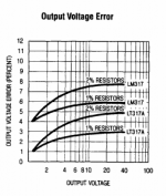
I've attached a plot from Linear Tech's LT317A series regulator - the principle is the same as for the TL431 except the bandgap sits at 1.25V rather than 2.5V. As the output voltage goes up so the error contribution from the resistors increases too.
Attachments
Sy,
Hence stacking references has not netted us an improvement in noise, it has only dis-improved the noise.
Ciao T
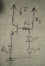
No, what SY said makes sense, for the current source shown below. Doubling the voltage makes you increase the degeneration resistance R1, reducing the gain by -6dB. Or as SY put it, increasing the signal by 6dB.
Lower gain means lower noise, since the noise only increases by 3dB, the overall circuit has 3dB lower noise.
Attachments
Last edited:
No, what SY said makes sense, for the current source shown below. Doubling the voltage makes you increase the degeneration resistance R1, reducing the gain by -6dB. Or as SY put it, increasing the signal by 6dB.
Lower gain means lower noise, since the noise only increases by 3dB, the overall circuit has 3dB lower noise.
It also makes sense for a normal voltage regulator that compares the output of a regulator to a reference. The voltage regulator amplifies the reference voltage- drop the gain by two, increase the reference voltage by two, and you have that 3dB noise advantage again. Yes, you could cover that up by incompetently specifying a noisy error amp, but that's the stuff of polemics and cartoons, not engineering analysis.
Jan,
Correct. So the regulator is inherently instable, unless compensated externally.
Simple and short.
Ciao T
The cap modifies the open loop amplitude and phase response to obtain sufficient phase/gain margin to make it stable when the regulation loop is closed. A simple case of compensation.
Correct. So the regulator is inherently instable, unless compensated externally.
Simple and short.
Ciao T
Hi,
Well, it seems I KNOW BETTER. I am rather familiar with feedback theory et al, hence it is a complete mystery how anyone would declare a feedback system without build-out network to be stable into capacitive loads.
However, that was not my point.
My point with Jan was that he in the same sentence claimed that regulators where stable and then also claimed they needed a load capacitor to be stable. The two really are mutually exclusive, irrgardless of the electronics involved, it is simple logic.
I measured it, the usual way.
JA in Stereophile independently confirmed my measurements and claims, incidentally and it was discussed here before, you where involved.
Again, why would anyone question a figure that clearly and accurately specified, if they understand the specifications and what they imply?
Using suitable equipment it is trivial to measure noise like this.
It is Equivalent Input Noise is of course measured on the output and then referred back to the input by subtracting the gain. You may wish to peruse Wikipedia and Rane's background information, if you still do not understand the term.
I think, given that this discussion was had before with PMA and PMA is well aware of this (as his post illustrates) and incidentally you also had to get in on this debate last time (so you should also know better) no answer is required.
Ciao T
This such rudimentary stuff Torsten and you should know better. Read the data sheet and study a bit feedback theory and compensation techniques as janneman suggests above.
Well, it seems I KNOW BETTER. I am rather familiar with feedback theory et al, hence it is a complete mystery how anyone would declare a feedback system without build-out network to be stable into capacitive loads.
However, that was not my point.
My point with Jan was that he in the same sentence claimed that regulators where stable and then also claimed they needed a load capacitor to be stable. The two really are mutually exclusive, irrgardless of the electronics involved, it is simple logic.
Re your -147 figure ref 1V, how do you arrive at such a low figure?
I measured it, the usual way.
JA in Stereophile independently confirmed my measurements and claims, incidentally and it was discussed here before, you where involved.
Anything below -120dBVA needs to be carefully qualified. Throwing figures like that around without an explanation is to be rightly questioned.
Again, why would anyone question a figure that clearly and accurately specified, if they understand the specifications and what they imply?
Using suitable equipment it is trivial to measure noise like this.
It is Equivalent Input Noise is of course measured on the output and then referred back to the input by subtracting the gain. You may wish to peruse Wikipedia and Rane's background information, if you still do not understand the term.
I think PMA is right to challenge you on this. Care to share the details?
I think, given that this discussion was had before with PMA and PMA is well aware of this (as his post illustrates) and incidentally you also had to get in on this debate last time (so you should also know better) no answer is required.
Ciao T
Hi,
Competently designed regulator circuits have an AC gain of unity across the bandwidth of interest. So in your case you have increased noise by 3dB, not reduced it.
Ciao T
It also makes sense for a normal voltage regulator that compares the output of a regulator to a reference. The voltage regulator amplifies the reference voltage- drop the gain by two, increase the reference voltage by two, and you have that 3dB noise advantage again.
Competently designed regulator circuits have an AC gain of unity across the bandwidth of interest. So in your case you have increased noise by 3dB, not reduced it.
Ciao T
Hi
You could get lower noise by using my suggestion of using an amplified zenner diode, using a suitable transistor (much lower noise than the reference).
In other words, use the lowest noise reference available and scale it with unity AC gain will be lower.
So no, it does not make sense in the context of competent design of the circuit.
Ciao T
No, what SY said makes sense, for the current source shown below. Doubling the voltage makes you increase the degeneration resistance R1, reducing the gain by -6dB. Or as SY put it, increasing the signal by 6dB.
You could get lower noise by using my suggestion of using an amplified zenner diode, using a suitable transistor (much lower noise than the reference).
In other words, use the lowest noise reference available and scale it with unity AC gain will be lower.
So no, it does not make sense in the context of competent design of the circuit.
Ciao T
Competently designed regulator circuits have an AC gain of unity across the bandwidth of interest. So in your case you have increased noise by 3dB, not reduced it.
Sometimes and no, respectively.
SY,
Wrong on both counts.
Show me any regulator circuit with stacked references and I can make it quieter by restructuring it to use only of the same.
And if it does not have unity gain at AC you do not minimise noise, so I can restructure the circuit to offer unity gain at AC.
Ciao T
Sometimes and no, respectively.
Wrong on both counts.
Show me any regulator circuit with stacked references and I can make it quieter by restructuring it to use only of the same.
And if it does not have unity gain at AC you do not minimise noise, so I can restructure the circuit to offer unity gain at AC.
Ciao T
So the above clearly states that the noise is input referred, A-weighted and 147dB below 1V. And no-one with a background in electronics should have any problems with it.
And to answer PMA's charge of being confusing, I use only internationally standardised measurements and ways to state that are unambiguous. But I guess you cannot please some people.
The reference is an absolute value of 1V , while it seems that you re
multiplying this value of 1V by the gain of your preamp thus your base
is no more 1V but 1V x Gain , for exemple 100V for a 40db gain preamp.
You cant change the reference of 1V by multiplying by 100
and still talk about -dBV that are in fact -dB100V.....
John,
If the regulator has unity gain at AC within the band of interest (and why would anyone deliberately create one with more than unity gain at AC?) then changing the reference voltage at DC changes nothing for the AC performance.
HOWEVER, the greater noise of the reference with stacked references will always cause higher noise.
The key is look at AC and DC behaviour independently, it will be very clear then. Somewhere there is of course a transition from AC behaviour to DC and this where we have the potential for improvements using staked references, however this should way below the bandwidth of interrest in competent designs.
Ciao T
T, I think you are missing something here. Changing the ref. Voltage changes the noise gain, because the regulator amp does not have to amplify as much, closed loop.
If the regulator has unity gain at AC within the band of interest (and why would anyone deliberately create one with more than unity gain at AC?) then changing the reference voltage at DC changes nothing for the AC performance.
HOWEVER, the greater noise of the reference with stacked references will always cause higher noise.
The key is look at AC and DC behaviour independently, it will be very clear then. Somewhere there is of course a transition from AC behaviour to DC and this where we have the potential for improvements using staked references, however this should way below the bandwidth of interrest in competent designs.
Ciao T
Hi,
PLEASE familiarise yourself with the way Equivalent Input Noise is measured, derived and specified. I do not have the time to educate you in absolutely basic stuff.
Anyway, you have no point.
Ciao T
The reference is an absolute value of 1V , while it seems that you re
multiplying this value of 1V by the gain of your preamp thus your base
is no more 1V but 1V x Gain , for exemple 100V for a 40db gain preamp.
You cant change the reference of 1V by multiplying by 100
and still talk about -dBV that are in fact -dB100V.....
PLEASE familiarise yourself with the way Equivalent Input Noise is measured, derived and specified. I do not have the time to educate you in absolutely basic stuff.
Anyway, you have no point.
Ciao T
- Status
- Not open for further replies.
- Home
- Member Areas
- The Lounge
- John Curl's Blowtorch preamplifier part II