that could be my new byline.GRollins said:I am forced to reply, "Hell, honey, have you had your DNA checked? I might very well be your father!"
") Can I borrow it?
Can I borrow it?bear said:yes, but you run the risk of putting the amp together with a source that has DC offset or output, then poof! Well maybe not poof, but you could develop some serious DC output from the amp... better to be safe than sorry.
_-_-bear
Hi bear
For safety purpose I think the input cap is necessary. There was an accident. I damaged one of my JVC woofer last week when I by-passed the output cap of my JC-2 clone pre-amp and now it needs re-cone service. But without the output cap which is a 2.2uF Wima MKP10 I feel the sonic quality of the pre-amp sounds better. The sound is more natural with no coupling caps.
Best Regards
john curl said:It is best to add servo.
Hi Mr. Curl
Thank you for your prompt reply again.
It is a good idea to add servo. It would be great if you can send me the schematic.
By the way, does a 500VA 25V x 2 (this is the closest voltage I can source from Farnell & RS) toroid transformer good enough for one channel?
Best Regards
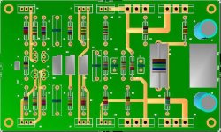
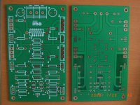
My pcb layout of John Curl's JC-3 power amp base on original circuit published except I eliminated the 5uF input capacitor as my JC-2 clone pre-amp already has an output cap.
JFets at the input stage will be 2SK170BL/2SJ74BL
Power transistors will be MJL3281/MJL1302 and the rest MJE15032/MJE15033. These transistors will be mounted on heat sinks.
Size of pcb is 5 x 3 inches.
JFets at the input stage will be 2SK170BL/2SJ74BL
Power transistors will be MJL3281/MJL1302 and the rest MJE15032/MJE15033. These transistors will be mounted on heat sinks.
Size of pcb is 5 x 3 inches.
Attachments
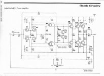
MikeW said:This amp should not be built to this schematic. There are improvements to be made. John has given hints along the way. Dimitri also has some improvements. It will no longer be a JC-3 but will sound better.
Hi Mike
Thank you for your comments.
Do you have the final schematic for me to study before I go ahead to make boards?
Best Regards

- Home
- Amplifiers
- Solid State
- John Curl amp