It's sleek-looking, for sure. Unless a better option appears, I'm leaning toward repurposing the chassis from this Systron pulse gen, with perforated top, sides, and bottom:
https://cdn11.bigcommerce.com/s-a1x...r-10.39__66606.1490150881.jpg?c=2?imbypass=on
https://cdn11.bigcommerce.com/s-a1x...r-10.39__66606.1490150881.jpg?c=2?imbypass=on
Lol, it is a Hammond 1455 series enclosure with a CNC'd aluminium plate in lieu of the plain top cover for ventilation. I've not committed to machine out the original top cover yet - you only get one go!
It does look similar to a BBQ smoker box, I'll give you that, but I swear that's not where I got the inspiration!
Seriously though, I find the Hammond boxes are easy to work with, look decent for not much $$ and can sink plenty of heat, even in the crazy Aussie summer heat. They come in multiple sizes and are usually well stocked at your favourite large vendor (Mouser, Farnell, Newark etc).
Next I'm gonna go design an overheating, unreliable amp, put it in this enclosure and call it the Smoke-Box
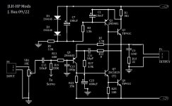
Here are the mods I have made to each channel over the last year or so. Along with improvements to the power supplies, and correcting some trace layout errors, this thing now sounds and measures really excellent for hp's 80 Ohms and up. And still does really well with lower-Z phones that have high sensitivity, like my 44 Ohm AKG's that are rated 109dB SPL/V. I still have not found an ideal enclosure for it...
(BTW, the part numbering is not mine, and doesn't match the pcb, which only has part values on it.)
(BTW, the part numbering is not mine, and doesn't match the pcb, which only has part values on it.)
Attachments
Last edited:
R19 to servo ?Here are the mods I have made to each channel over the last year or so. Along with improvements to the power supplies, and correcting some trace layout errors, this thing now sounds and measures really excellent for hp's 80 Ohms and up. And still does really well with lower-Z phones that have high sensitivity, like my 44 Ohm AKG's that are rated 109dB SPL/V. I still have not found an ideal enclosure for it...
(BTW, the part numbering is not mine, and doesn't match the pcb, which only has part values on it.)
R19 to servo ?
Yes, I'm pretty sure that has been discussed earlier in this thread, as the best way to deal with the circuit's huge temperature sensitivity. Of course, you can use the standard input bias scheme if you wish.

I thought I'd add: I've had the servo in the circuit for a couple months, and I do not find it essential. Having it is more about convenience and peace-of-mind: I no longer have to wait 30 minutes before plugging headphones in. The fact is, servo or not, the amp doesn't sound its best until it is warmed up (the beta of the outputs increases significantly at operating temp) . So either way you'll probably give it 30 minutes or so before doing any serious listening.
Do i cut the main ground plane in half? where the 2 cut lines are shown. Or do I just cut partly?Aagh! I just realized that the picture I posted earlier with the cuts and jumpers to fix the hum problem was incomplete! The description was correct, but I forgot to show the changes for the regulator ground connections. A senior moment... my apologies.
The corrected pic is attached. BTW, the wires are shown curved only to avoid the other text. I would use as heavy gauge wire as you can tolerate for these reg gnd jumpers. I used 18. Oh, and insulate them, of course...
Partly. Those cuts are as long as the marks. There are a couple more cuts and jumps to make, to correct other grounding errors. I'll post an updated pic in the next day or two.Do i cut the main ground plane in half? where the 2 cut lines are shown. Or do I just cut partly?
The most important one is already shown in post #888: https://www.diyaudio.com/community/attachments/gndmods-jpg.945986/
Last edited:
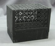
Speaking of vented enclosures... I just found a couple of these buried in the back of a shelf, where I stashed them 20+ years ago... an old-school chassis for tube amps! Complete with black-crinkle finish (powdercoating?) and a chrome handle for the top... not sure I can get the pcb to fit in it but it certainly is ventilated and has vintage appeal !!
(BTW, if you search DIYAudio for "vented enclosures", all you get is posts about speaker cabinets.)
(BTW, if you search DIYAudio for "vented enclosures", all you get is posts about speaker cabinets.)
Attachments
After months of looking, I FINALLY found a good enclosure to house the JLH headphone amp. I posted details in the Parts forum:
https://www.diyaudio.com/community/...-enclosure-for-small-class-a-projects.394852/
https://www.diyaudio.com/community/...-enclosure-for-small-class-a-projects.394852/
Back to the roots
I would like to say a big thank you to all the diyAudio fans who have done many years of well documented work in the JLH thread. It has been great fun following your recommendations.
I was looking for a hobby project a few months ago. I will be retiring soon. And so I stumbled across the JLH kit. It was the year . I got my first electronics kit for Christmas in 1969. And then there was this forum. So it was clear even before ordering the kit that it was not just about soldering a kit together.
I followed all the recommendations and can only recommend to all who are considering to build this kit to integrate a servo and especially to make the changes to the ground potential on the board.
As servo IC (I have tried very many) I recommend TL071 (61/81). The OP Amp only needs a trimmer and you can set 0,0001 V. Also it is very fast after power on in this range.
Speaker protection and delay I implemented with UPC1237.
Another important note: The supplied transistors have a different pinout than replacement types. This explains the error that was solved some time ago by using other transistor types.
I used BC550 and BC560.
Here's the updated pic.
View attachment 1099430
The upper cuts/jumps moves the regulator ground pins to the post-reg filter caps.
The other one corrects an error where the feedback shunt resistor was sharing a ground trace with the output ground.
Nicely done!
For any that are interested, I found the original HiFi News & Record Review January 1979 article, together with an update six months later, tucked in with some college notes from nearly 45 years ago; I scanned it yesterday. It's not on World Radio History, more's the pity. Enjoy.
The 'missing' pages were simply advertising; I removed them to keep down the file size. I have no idea what was on the July 1979 issue, page 53; I hadn't kept it; I guess it was just News continued.
The 'missing' pages were simply advertising; I removed them to keep down the file size. I have no idea what was on the July 1979 issue, page 53; I hadn't kept it; I guess it was just News continued.
Attachments
@GerardLardner
Ha!
I built that as one of my first projects with a PCB that I made from their artwork.
I remember taking it into a local HiFi shop that had a "bring in your equipment and we'll test it out" day. Distortion was un-measurable as I recall. (I thought that more to do with the resolving power -- or lack thereof -- of their equipment)
I wonder where that amp is now...
- Home
- Amplifiers
- Headphone Systems
- JLH Headphone Amp