You obviously don't want to hook up your 230V~ mains to either of the 115V~ windings, but labeling is clear enough. (Hooking up secondaries can be trickier, but all that happens if you do it out of phase is no output voltage to speak of.) BTW, you also want a mains fuse. Like 250 mA T or so.Thanks. I will do some more research as hooking the primaries up the wrong way is potentially a transformer killer.
The latter, i.e. circuit ground.By power ground are you refering to mains gnd (ie) IEC-socket or cap bank gnd?
I remember reading that outlets without a PE connection were used a lot longer in Sweden than they were down here (where I don't think any installation dating from about the mid-late 1960s and after still has this sort of thing)? Anyway, that's not good. The instructions for any kind of IEC Class I equipment usually state pretty clearly that it must be used on a grounded outlet. So "officially" you cannot even use an ordinary PC, laser printer, or whatnot.Unfortunenatly the only grounded outlets in my apartement is the ones in the kitchen, thus GND is floating between the equipment hooked up to the 6-way grounded extension chord I'm using by the PC.
That's the mains filter caps in the PC power supply (and possibly other supplies like monitor and whatnot). There's usually about 1 nF per device going from both live and neutral to PE, so you have some capacitive coupling to half mains voltage (unless it's "technical" mains using two out-of-phase voltages).Suppose I could hook up a groundwire to the radiator next to the PC (water pipes going in to the litteral ground)...but there's a small difference in the gnd potential. It can be felt as a tingeling feeling if touching the PC chassis and the radiator at the same time...
As it stands, you are probably best off going for a Class II (double insulated) kind of construction with no PE connection at all and a (premade) 2-wire mains cable. Takes some more care in construction to ensure that "no single insulation fault can cause any harm". A metal case would be connected to star ground, once directly and typically via ~10 nF to circuit ground at inputs and outputs; having (sub-)star ground at the input jacks avoids having to insulate them, which is why equipment mfrs often do that (it's way cheaper if you have a gazillion input jacks).
While water pipes can be useful in obtaining a half-decent earth connection, you can never be totally sure. What if there's a piece of PVC pipe in exactly the wrong spot?
You may want to consider an electrician about what can be done in an unsatisfactory situation like this.
Last edited:
You obviously don't want to hook up your 230V~ mains to either of the 115V~ windings, but labeling is clear enough. (Hooking up secondaries can be trickier, but all that happens if you do it out of phase is no output voltage to speak of.) BTW, you also want a mains fuse. Like 250 mA T or so.
The latter, i.e. circuit ground.
I remember reading that outlets without a PE connection were used a lot longer in Sweden than they were down here (where I don't think any installation dating from about the mid-late 1960s and after still has this sort of thing)? Anyway, that's not good. The instructions for any kind of IEC Class I equipment usually state pretty clearly that it must be used on a grounded outlet. So "officially" you cannot even use an ordinary PC, laser printer, or whatnot.
That's the mains filter caps in the PC power supply (and possibly other supplies like monitor and whatnot). There's usually about 1 nF per device going from both live and neutral to PE, so you have some capacitive coupling to half mains voltage (unless it's "technical" mains using two out-of-phase voltages).
As it stands, you are probably best off going for a Class II (double insulated) kind of construction with no PE connection at all and a (premade) 2-wire mains cable. Takes some more care in construction to ensure that "no single insulation fault can cause any harm". A metal case would be connected to star ground, once directly and typically via ~10 nF to circuit ground at inputs and outputs; having (sub-)star ground at the input jacks avoids having to insulate them, which is why equipment mfrs often do that (it's way cheaper if you have a gazillion input jacks).
While water pipes can be useful in obtaining a half-decent earth connection, you can never be totally sure. What if there's a piece of PVC pipe in exactly the wrong spot?
You may want to consider an electrician about what can be done in an unsatisfactory situation like this.
It seems the most simple way to hook-up the headphone system is to only use star-gnd in both enclosures(headamp and DAC), leaving gnd-tab on the IEC-sockets NC.
As for isolating the RCA-jacks, I've always done that anyway and tested with DMM to make sure there's no contact between sgn.gnd and chassis.
R-Core shield wire to Cap Bank gnd, that in turn meets the other gnd's at the stargnd(including sign.gnd).
As for the secondaries..as long as I connect wht-wht to to one full bridge rectifier(4x1N4007+4x100nF snubber caps) and org-org to another..I should be ok?
Is the ~10nF caps from signal-gnd(RCA-IN/RCA-OUT) to stargnd necessary?
If it is, no problem, I have a large collection of Philips film caps from 1nF to 18nF. I don't have any ceramics that small I think, I do have alot of them as I usually swap them for Wimas or similar when getting a kit of some sort that I build.
IF I encounter groundloop problems, I could lift signal-gnd via a resistor(~100R)?
Have I missed anything?
Gotten anything wrong?
A 2-pin version of that IEC jack also exists, but yeah. For "small-fry" electronics like that you could also use a simple "figure 8" jack (Telefunken, I am sure Wikipedia will tell you the official name), which should be only marginally less common. I don't think you can get those with an integrated fuse holder though.It seems the most simple way to hook-up the headphone system is to only use star-gnd in both enclosures(headamp and DAC), leaving gnd-tab on the IEC-sockets NC.
How do you plan on doing primary-side transformer wiring? A bit more care is required for a Class II device. Ideally the mains cable would run almost directly up the the transformer. That, or you'd use a PCB-mounted jack (with PCB routing giving adequate insulation, and maybe the odd spark gap).
BTW, if you plan on doing a DAC with integrated power supply, you are actually more brave than entry-level DAC makers, who tend to outsource this task (and responsibility) and buy premade SMPS wall-warts from specialized manufacturers, figuring that they couldn't come up with anything remotely as good in safety, efficiency and EMI and as cheap by themselves (which is probably true).
(Have you considered combining both in one case? DACs tend not to be too big or require massive transformers, so that might still squeeze in.)
Speaking of DACs, you may consider doing that as a Class I (safety earthed) device if it only ever connects to the (floating) headphone amp and has all galvanically isolated inputs (Toslink, coaxial with transformer).
The problem is that you have to join both windings in the power supply, and that those are directional. If you connect them in opposite directions, their voltages just about cancel, and effective inductance drops significantly (the same effect used in a common-mode choke). Easy enough to find out with a multimeter though - join 1x wht and 1x org, measure AC on the other two (>30 VAC --> OK). There's a 50/50 chance of getting it right.As for the secondaries..as long as I connect wht-wht to to one full bridge rectifier(4x1N4007+4x100nF snubber caps) and org-org to another..I should be ok?
Films also work, ceramics merely tend to have less inductance.Is the ~10nF caps from signal-gnd(RCA-IN/RCA-OUT) to stargnd necessary?
If it is, no problem, I have a large collection of Philips film caps from 1nF to 18nF.
These go from jack GND directly to case (chassis)! Chassis is later connected to stargnd. Star grounding only ever works at low frequencies due to inductance, at RF you want as many low-inductance connections as possible so your case can act as a Faraday cage.
Honestly, I have no idea where you're envisioning to do that, now that your amp is supposed to have no PE connection at all.IF I encounter groundloop problems, I could lift signal-gnd via a resistor(~100R)?
Last edited:
I've gotten a little bit further on this build.
Attentuator to headamp wiring is shielded CAT5 cable with the shield connected on the attentuator-PCB.
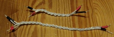
Braided wire is 99.99% silver in PTFE tubing. I'll use that between headamp and headphone jack.
Speaking of headphones, I've told a seller(another forum) that I'll buy his used , but in mint condition, Senn HD600's (300ohm).
Just waiting for confirmation etc.
Still to do is:
Solder in & out on the DC-servo.
Solder in the output wires.
Rectifier/voltage regulators (I'll use two LT1083CP's atleast for now, just waiting for some parts)
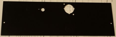
Cover unused holes on the front.
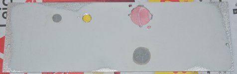
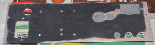
Paint white parts black. Chassis came two-coloured.
If it's not really obvious, I'm not good at metal or wood working and I don't really like doing it either.
GND pin on the IEC is not connected, RCA etc are isolated from chassis.
Attentuator is wired as is because I want to be able to easily remove it and use it in other headamps until I find the headamp that I'll stick with.
Should I have additional capacitance( there are 4x 2200uF on the PCB)?
If so, I'm left with the option of putting them after the Vregs as they have limited space and also handle rectification.
I know I've read the answer to this question somewhere already, but I can't find it now...
Before popping the OPA2134 in the socket, I should trim offset as low as I can right?
Start with the trimpots turned fully CW or CCW and then trim until I get as low offset as possible without the DC-servo?
Does it matter if all connections are made? To an empty DIP8 socket that would be.
That is: is it ok to have the DC-servo board connected to power(pos gnd neg), inputs and outputs to the board connected...only no opamp in the socket? Or should I hold off soldering the connections to the DC-servo PCB until I've trimmed offset as much as possible manually?
Attentuator to headamp wiring is shielded CAT5 cable with the shield connected on the attentuator-PCB.
Braided wire is 99.99% silver in PTFE tubing. I'll use that between headamp and headphone jack.
Speaking of headphones, I've told a seller(another forum) that I'll buy his used , but in mint condition, Senn HD600's (300ohm).
Just waiting for confirmation etc.
Still to do is:
Solder in & out on the DC-servo.
Solder in the output wires.
Rectifier/voltage regulators (I'll use two LT1083CP's atleast for now, just waiting for some parts)
Cover unused holes on the front.
Paint white parts black. Chassis came two-coloured.
If it's not really obvious, I'm not good at metal or wood working and I don't really like doing it either.
GND pin on the IEC is not connected, RCA etc are isolated from chassis.
Attentuator is wired as is because I want to be able to easily remove it and use it in other headamps until I find the headamp that I'll stick with.
Should I have additional capacitance( there are 4x 2200uF on the PCB)?
If so, I'm left with the option of putting them after the Vregs as they have limited space and also handle rectification.
I know I've read the answer to this question somewhere already, but I can't find it now...
Before popping the OPA2134 in the socket, I should trim offset as low as I can right?
Start with the trimpots turned fully CW or CCW and then trim until I get as low offset as possible without the DC-servo?
Does it matter if all connections are made? To an empty DIP8 socket that would be.
That is: is it ok to have the DC-servo board connected to power(pos gnd neg), inputs and outputs to the board connected...only no opamp in the socket? Or should I hold off soldering the connections to the DC-servo PCB until I've trimmed offset as much as possible manually?
Attachments
-
 Output_wiring_silver_PTFE_1.jpg46.1 KB · Views: 626
 -
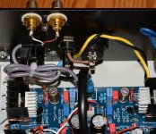
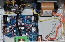 JLH_Headamp_populating_18.jpg339.8 KB · Views: 620
 -
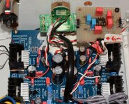
 JLH_Headamp_populating_17.jpg250.7 KB · Views: 605
 -
 JLH_Headamp_populating_14.jpg220.5 KB · Views: 595
 -
 JLH_Headamp_populating_24.jpg235.9 KB · Views: 600
 -
 JLH_Headamp_populating_25.jpg339.5 KB · Views: 336
Silver in teflon wiring? Were you planning to wind RF transformers or something? Anyway, it won't matter.
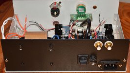
A bit of an unfortunate connector layout at the back there. I would much rather like to see the IEC connector on the other side of the fuseholder, so audio wiring is as far away from mains wiring as possible. IMHO this would never pass any safety approval like that.
A bit of an unfortunate connector layout at the back there. I would much rather like to see the IEC connector on the other side of the fuseholder, so audio wiring is as far away from mains wiring as possible. IMHO this would never pass any safety approval like that.
Silver in teflon wiring? Were you planning to wind RF transformers or something? Anyway, it won't matter.
A bit of an unfortunate connector layout at the back there. I would much rather like to see the IEC connector on the other side of the fuseholder, so audio wiring is as far away from mains wiring as possible. IMHO this would never pass any safety approval like that.
Silver in PTFE,
Been using that for a few years to make interconnects.
Yes, the layout on the backplate is not optimum. I used the existing layout and added the RCA jacks.
I'm not building my projects to sell, only for personal use so as long as they are safe enough for that I'm ok.
I think I'll put together a quick LM3x7T dual rail supply tomorrow after painting the white parts of the chassis black.
I'm eager to test this thing.
I just bought a pair of Philips Fidelio X2's last night. Got them at a steal (IMHO) at about $160 on sale.
They sold out in hours from a stock of "more than 60".
I'm eager to test this thing.
I just bought a pair of Philips Fidelio X2's last night. Got them at a steal (IMHO) at about $160 on sale.
They sold out in hours from a stock of "more than 60".
Well didn't complete the vregs.
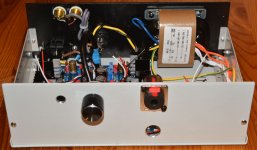
But I did fix the unused holes in the front panel and painted it black like the rest of the chassis.
But I did fix the unused holes in the front panel and painted it black like the rest of the chassis.
Attachments
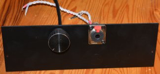
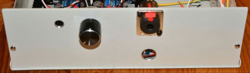
PE pin on the IEC connector MUST be connected to the metal case ! Certainly with DIY stuff. You are asking of safety problems here. I read that you don't have PE in your home, well you should have PE for your own and your families safety. Also very unfortunate layout with regards to mixing 230V IEC socket and audio inputs.... Why mix low voltage signaling with 230 V AC wiring ? Don't be surprised if it picks up 50 Hz hum. It seems like you are good with metal but just make lazy decisions (which always cost more time eventually). You could have saved yourself time by taking 5 minutes "dry testing" parts and boards in the case and determine the right locations for optimal cable routing and least hum interference. No silver in PTFE cable can make up for such sloppiness.
If you move the power switch to the right side of the front and the IEC socket to the right side of the transformer on attached picture it will be way better. Switching devices at the back is not ergonomical")
If you move the power switch to the right side of the front and the IEC socket to the right side of the transformer on attached picture it will be way better. Switching devices at the back is not ergonomical
Attachments

Last edited:
PE pin on the IEC connector MUST be connected to the metal case ! Certainly with DIY stuff. You are asking of safety problems here. I read that you don't have PE in your home, well you should have PE for your own and your families safety. Also very unfortunate layout with regards to mixing 230V IEC socket and audio inputs.... Why mix low voltage signaling with 230 V AC wiring ? Don't be surprised if it picks up 50 Hz hum. It seems like you are good with metal but just make lazy decisions (which always cost more time eventually). You could have saved yourself time by taking 5 minutes "dry testing" parts and boards in the case and determine the right locations for optimal cable routing and least hum interference. No silver in PTFE cable can make up for such sloppiness.
If you move the power switch to the right side of the front and the IEC socket to the right side of the transformer on attached picture it will be way better. Switching devices at the back is not ergonomical
I simply used the holes already there from when I used the chassis for an USB DAC.
Might just do as you and a previous poster suggest since I already has everything out needed to do it.
Regarding the (un)grounded mains, I can't do a thing about that as I rent my apartement.
You are in Sweden. I guess there is a law for electrical safety too in Sweden. You could point out to the landlord that you need PE in your house. Check your local regulations, I can not imagine a Western European country (?) has no laws on electrical safety.
The situation now is that every device in your house that has a mains filter (pc, washing machine etc. ) will have half of the mains voltage on the metal case. Please test it ! Now imagine a 230V wire being loose and touching the metal case.
Aha, I see you already noticed. I just reread some previous pages:
This calls for action, you need PE. It is very unwise to use a distributor designed for use with PE in a wall socket without PE as all devices connected will be connected unsafely/unprotected. You can however use non-PE 2 prong cords in PE wall sockets. Those are class II devices.
The situation now is that every device in your house that has a mains filter (pc, washing machine etc. ) will have half of the mains voltage on the metal case. Please test it ! Now imagine a 230V wire being loose and touching the metal case.
Aha, I see you already noticed. I just reread some previous pages:
Unfortunately the only grounded outlets in my apartment are the ones in the kitchen, thus GND is floating between the equipment hooked up to the 6-way grounded extension chord I'm using by the PC.
Suppose I could hook up a groundwire to the radiator next to the PC (water pipes going in to the litteral ground)...but there's a small difference in the gnd potential. It can be felt as a tingeling feeling if touching the PC chassis and the radiator at the same time...
This calls for action, you need PE. It is very unwise to use a distributor designed for use with PE in a wall socket without PE as all devices connected will be connected unsafely/unprotected. You can however use non-PE 2 prong cords in PE wall sockets. Those are class II devices.
Last edited:
You are in Sweden. I guess there is a law for electrical safety too in Sweden. You could point out to the landlord that you need PE in your house. Check your local regulations, I can not imagine a Western European country (?) has no laws on electrical safety.
The situation now is that every device in your house that has a mains filter (pc, washing machine etc. ) will have half of the mains voltage on the metal case. Please test it ! Now imagine a 230V wire being loose and touching the metal case.
Aha, I see you already noticed. I just reread some previous pages:
This calls for action, you need PE. It is very unwise to use a distributor designed for use with PE in a wall socket without PE as all devices connected will be connected unsafely/unprotected. You can however use non-PE 2 prong cords in PE wall sockets. Those are class II devices.
First, thanks for the compliment on my metal work. It's the first time I've covered holes and painted anything audio related.
My landlord is actually the largest here and was owned by the state before.
I highly doubt they'd spend the $$ on re-wiring a large number of apartements.
That leaves me with the option of not using mains gnd.
(however I will look into the regulations for landlords, apartements and mains ground)
The "figure 8" sockets that have been suggested, could I not just use regular IEC (got plenty of those cables) and use a non-grounded distributor?
That would have the same effect as a 2 lead mains cable?
BTW, Imagine all comercial equipment being sold with IEC sockets and grounded power cable, computers etc...
In over 400 apartements here, as long as they arent all installed in the kitchen, those are all connected to non-grounded outlets...possibly and probably via grounded distributor.
I'll look into swapping the back panel layout around today. The fiancé won't be thrilled about me working with chemical metal(plastic metal) again though lol.
That stuff really stinks no matter how well ventilated the work area is.
Better, it more or less follows common standards.
Even if the landlord is the largest there still are laws regarding electrical safety and as a renter you have rights. It just can't be that you have an unsafe electrical installation. Almost all household devices and computers need a PE connection. Here there often is a yellow/green wire behind the wall outlet but the landlord decided to use non PE wall outlets.Sometimes PE wire is in the ceiling where cables are divided to lamps and switches. Please have this checked by an electrician or a certified person. It is not hard to add a new wire to a wall outlet when PVC piping is used. A new PE wall outlet is not expensive.
I suppose you also call it ground as it is the same word for earth in Swedish ? We do the same in our language but it does not make stuff easier. Let's call it Protective Earth (PE) and audio ground GND. They are 2 different things.
BTW, Imagine all commercial equipment being sold with IEC sockets and grounded power cable, computers etc...
In over 400 apartements here, as long as they arent all installed in the kitchen, those are all connected to non-grounded outlets...possibly and probably via grounded distributor.
Even if the landlord is the largest there still are laws regarding electrical safety and as a renter you have rights. It just can't be that you have an unsafe electrical installation. Almost all household devices and computers need a PE connection. Here there often is a yellow/green wire behind the wall outlet but the landlord decided to use non PE wall outlets.Sometimes PE wire is in the ceiling where cables are divided to lamps and switches. Please have this checked by an electrician or a certified person. It is not hard to add a new wire to a wall outlet when PVC piping is used. A new PE wall outlet is not expensive.
I suppose you also call it ground as it is the same word for earth in Swedish ? We do the same in our language but it does not make stuff easier. Let's call it Protective Earth (PE) and audio ground GND. They are 2 different things.
Attachments
Last edited:
Better, it more or less follows common standards.
Even if the landlord is the largest there still are laws regarding electrical safety and as a renter you have rights. It just can't be that you have an unsafe electrical installation. Almost all household devices and computers need a PE connection. Here there often is a yellow/green wire behind the wall outlet but the landlord decided to use non PE wall outlets.Sometimes PE wire is in the ceiling where cables are divided to lamps and switches. Please have this checked by an electrician or a certified person. It is not hard to add a new wire to a wall outlet when PVC piping is used. A new PE wall outlet is not expensive.
I suppose you also call it ground as it is the same word for earth in Swedish ? We do the same in our language but it does not make stuff easier. Let's call it Protective Earth (PE) and audio ground GND. They are 2 different things.
Well I checked with the guy doing the upkeep of the apartements in my neighbourhood, no PE drawn at all except kitchen.
Yes there's a law about new constructions (houses, apartements) but not for existing buildings.
So, I'm stuck with what I've got...atleast until we move. We do plan on doing that when the fiancé gets pregnant.
I would expect that all new and recent houses have PE brought to every power point, socket or fixed outlet.
I suspect that these newish regulations cannot be made retrospective for a house owner.
I have a sneeky feeling that for rented housing the law may be different. There may be a requirement to bring the house up to some acceptable electrical safety standard before the Landlord is allowed to rent out !
Do you have the equivalent to "trading standards", the authority that looks after the rights of buyers, or "building control" looking at safety of the construction and occupation of all housing?
Last edited:
I'll look up the regulations on monday.
Just adjusted my temporary lm3x7 dual rail supply.
After a while the R-Core xformer started making some mechanical buzz noise.
I have not connected it's screen to psu GND yet as the load resistors pretty much fills the screw terminals.
It's a "30W" 2x15VAC 1.5A (dual secondary) xformer.
I'm using the same load resistors that I used to adjusted a dual rail LT1083 supply I perf boarded a while ago.
What could cause this buzzing?
The perf board dual rail lm3x7 supply works as it should.
Black & yellow wires are used to mains (0-230VAC), blue is insulated with shrink tube(115VAC) and left un-connected.
I've heard mechanical buzz noise from transformers before, but that was from the output transformers on a tube amp I fixed and modified slightly.
Cheap chinese tube amp so I figured the output transformers were undersized.
That can hardly be the case now, only having resistors as load while adjusting the vregs?
PSU loaded with just load resistors ? What value ? Let's say if you use 10 Ohm then you already have 1.5 A.....and 30W power dissipation.
Technicians need values to determine matters.
Of course, I should have posted resistor values.
I use two 390R in parallell per rail, so 195R between each rail and gnd.
Voltage ?
No data = no answer or solution. Please adhere to the secret code of men: describe stuff so that other men understand. In order to be amongst "us" you need to give all necessary data "we" need to solve the problem (i.e. "your" problem).
Otherwise we go down to the level:
- "my car does not work"
- What does not work ?
- "I don't know it just does not work"
- What exactly does not work then ?
- "I hate that car"
As a fellow man I can only advise you to stay away from that level as it will only bring frustration and anger. You will feel disrespected, start eating large amounts of food, become fat and ask your partner if you are still thin while you aren't anymore and you will buy many pairs of shoes. End of DIY too.
Last edited:
- Home
- Amplifiers
- Headphone Systems
- JLH Headphone Amp