Hello from Tassie.
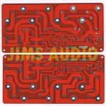
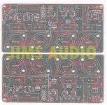
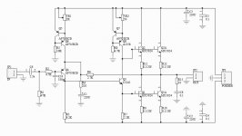
I purchased 4 of Jim's Audio pcb's to make a later version, dual-rail JLH amp; the schematic an pictures are attached below.
*It is my intention to use a 200VA 12+12 transformer to run all four.
*I would like to use some 2n3055 output transistors that I have on hand.
*I would like to use some 2n3019npn & 4033pnp l.f. driver transistors that I have on hand also. A970 are great for me too.
My plan is to run tight +-14VDC regulated rails, if I can squeeze it out without too much ripple. I'm going to use the big 7.5A regulator LT1083 inbetween two 10mF caps on each rail. I will incorporate a trimmer in to the feedback loop to adjust from say 12-16V and go from there.
Vpk for a 12W amp module is 12V
Ipk for the same amp is 2A.
There are four output transistors in the schematic below, two for current control and two to throw the volts up and down - they are rated at 250V and 16 Amps! which seems a little over the top for my humble machine! and at $3-5 a pop they are far too expensive because the boards not only use these hefty devices, they are doubled-up also. Meaning that, I need 16 output devices for my 4 amps if I use the paralelled devices shown on the schematic.
The two modules that will be driving my tweeters may be quite happy to run on just 2 devices per board. Any ideas welcome. This brings me to the next question.
Thermal considerations: The output transistors specified in Jim's original schematic have a junction to case thermal resistance of 0.7degC/W. And the ones I want to use have a resistance J>C of ~ 1.25degC / W.
Question1; Which transistor of the two will run cooler given a matching heat-sink and operating conditions?
My heatsinks; I have two largish heatsinks of about 0.3degC/w and intend to mount one bass and one treble amp module onto them using a machined 40mm x 6mm angle bracket for max surface contact.
Question4; Exactly how hot will my heatsink be using the data I have supplied?
Question2; Are the 2n3019npn & 4033pnp a fairly good substitute for the C3421 & A1358 ( labelled C3241 on the schematic!)?? I want to go with the tin can drivers because they look vintage (silly, I know...), but if they wont cut the mustard then they can stay in the box and then I will use bd139 or 2sd699 or MJE340 perhaps - any ideas are welcome, what's your favourite driver for this application?
I know that I am asking a lot of questions here, so if each of you could just have a stab at any one question, or make a comment, then I will eventually get there. I am in no hurry and I really do need a bit of help.
I am a wood machinist and joiner by trade and I have made a few stab-in-the-dark assuptions here, based on my limited knowledge, so please rip me into gear in the places where I got it wrong!
Thanks again; farmerjack
Attachments
Last edited:
Nice plans and fair questions but are you sure that following the regulators with 10mF caps is a good idea? Hint: peak charging current and regulator response.
If you are going to have regulation, it may as well work properly, particularly for the negative rail where the front end is prone.
If you are going to have regulation, it may as well work properly, particularly for the negative rail where the front end is prone.
Nice plans and fair questions but are you sure that following the regulators with 10mF caps is a good idea? Hint: peak charging current and regulator response.
If you are going to have regulation, it may as well work properly, particularly for the negative rail where the front end is prone.
Hello Ian, I hope you are experiencing some better weather up in the land of the great banana. Last night, here in Devonport (apple country)! I went to bed early, only to be woken with a start. A huge bang.
I arose in a deshevelled state to find my front door wide open and a heap of dust floating around. I think my house may have been struck by lightning!
I am thinking about heading up north soon to study electronics engineering at USQ. I could try to do it by correspondance but I have a mate here doing the same course, and he is struggling without the peer support.
I have been thinking about what you said about the caps and wonder if it would be better to put my regulator after the two big caps and before an 820 - 2200uF cap which the regulator can replenish sooner.
Cheers, and bye for now, Phil
Wow, never heard of that sort of lightning strike 
Yup, weather is balmy for the start of spring and skies clear blue here. I'd be out for a surf if the water temp, wasn't still icy. USQ is a good campus but it's different to Tassie in every way. I threw in a scientific career for woodturning but I still wish you every success in your studies - it's a great journey.
The biggest caps. on the amp side, which should be placed close to the output transistors, don't have much benefit over a few hundred uF and that applies to class AB at higher, 50-100W rating. Here you have only around 10W, so the cap could be smaller still. I know it's fashionable to shoehorn in the most humongous caps that can fit but there is a line between useful and wishful thinking.
Spend up and put a couple of nice, low ESR, max. 330 uF beauties like Panasonic FCs or the equivalent in the usual faves from Nichicon, Elna, Rubycon etc. - right on the relevant transistor lead if possible. Actually, when you look at three terminal reg application notes, the maximum cap. normally seen at the reg. output is only in the order of 10uF, to ensure the reg. can beat any likely error and give optimum ripple reduction. Otherwise, regulation becomes decreasingly effective as a noise filter.
Hi Farmerjack.....greetings from Brisbane.
Just a thought. Have you tried running your questions etc through the other big JLH thread?
It is called "JLH 10 watt Class A amplifier" or something very similiar.
It is quite large (around 2,500 posts) and all the JLH "Heavy hitters", 1969 and 1996 versions hang out there....just a thought. Also have you seen Geoff Moss's site? Just Google "class A amp site" and it should pop up. It is 99% devoted to this amp'.
Cheers, Jonathan
Hi Farmerjack.....greetings from Brisbane.
Just a thought. Have you tried running your questions etc through the other big JLH thread?
Cheers, Jonathan
Hi there John. I will go there now. Actually I will go there tonight after I clean up all the horizontal trees on my mates block. Had a bit of a breeze last night.
Can you tell me the name of that book about the mastadons.
Cheers Phil
Just so there is no claim against me under any false advertising law the book is not about mastadons!
It is a quote (very slight misquote I realised later, actually) from one of the works of the English author P.G. Wodehouse. Died about 1972. He wrote something like 94 books I think. I have about 57/58 last count. To narrow the search down a bit it was definitely one in the Jeeves/Bertie Wooster series so that reduces the sample size to around 10 I suspect. Those who study Wodehouse maintain that he had a phobia about aunts as they turn up frequently and almost always in a "bad light" with the sole exception of his robust "good and deserving" aunt Dahlia Travers. She's one of the great creations of English literature........Wodehouse himself was "farmed out" as a child to aunts in England by his parents who were stationed in India. The amateur psychologists have a field day. His most distressing Aunt is the fierce Agatha Gregson wife of the delightfully named Spencer Gregson.
So that is the best I can do at the moment. I re-read them every few years so will try and remember to post when I find it again!!!!!
Last edited:
Hi Ian thanks, appreciate that. It was going to take a LONG time to track it down "manually". I am suitably penitent and have amended the quote. I normally have a good memory but when I re-read it some time ago I realised it was wrong. I suspect I confused "mastodons" with "mammoths" and subconsciously subsituted "frozen wastes" for swamp.
I would hate to misquote Wodehouse as, like many others, he does more for my mental heath than just about anything else and millions upon millions like myself owe him a large a debt of gratitude.
But as they say; "It is the cracked people of the world who let the light in!"
Cheers, Jonathan
I would hate to misquote Wodehouse as, like many others, he does more for my mental heath than just about anything else and millions upon millions like myself owe him a large a debt of gratitude.
But as they say; "It is the cracked people of the world who let the light in!"
Cheers, Jonathan
Last edited:
What was the topic again?
Question 1 asked "how hot does my 0.3 deg C/W heatsink get?"
Assuming the numbers you quote are going to be 14 volt rails and say, 2A quiescent current, you have 28V*2A*2 output stages of power to be disssipated in quiescent conditions. With no margins, that's 112W which results in a 34 degree temp. rise so, on a 30 degree day and even with good venrilation, it gets hot, like 64 degrees and too hot to be around, let alone keep your finger on. It's simple enough to plug in any other numbers you choose to get suitable conditions here.
Note. This is for 2 similar amplifiers on the same sink. If you are using a local Oz. Conrad heatsink, with flat rear surface, the rating is closer to 0.38 deg/W for the 300mm length and temperature rise will be an uncomfortable 42 degrees - too much, I think.
Dissipation requirements are still well within the ratings of 2N3055 SOA diagrams, so there is no issue with components as they are rated to 4A at 28V DC by thermal limit. http://www.onsemi.com/pub_link/Collateral/2N3055-D.PDF, as long as you use genuine or second source parts and space them out for optimum heat removal and there is enough "coolth" with the types in use. I think you'd have to base your thermal calcs. on quiescent (worst case) conditions.
Maths
So, If I understand correctly, my formula to calculate the temperature of any given heatsink should be;
Temmperature rise of sink = Volts x Amps x Rj>c x Rhs>ambient
When volts are volts, amps are amps, Rj>c is the thermal resistance within the output transistor and finally Rhs>ambient is the cooling factor of the sink (in degrees celcius per watt).
Therefore if it ever reaches 30 degrees celcius in Devonport and I am using the amp and sink just described (14V @ 2A, 0.39deg/W) but decide to go for the expensive transistors which have a Rj>c of 0.7deg/W, then;
E x I x Rj>c x Rhs>ambient = temp rise
& temp rise plus ambient = temp of hs surface.
Now, substituting the figures;-
28 x 2 x 0.7 x 0.39 = a rise of 15degC
& 15 + 30 = a surface temp of 45deg C
If I were running the ol faithful 3055 on the same day my sink will be;-
28 * 2 * 1.52 * 0.39 = a rise of 33degC
& 33 + 30 = a surface temp of 63degC
So, now I draw the conclusion that the 2N3055 is quite a hot device compared to the MJ15024.
This is what I was alluding to, and my question should have been, which device runs cooler, and of course it is the more expensive of the two.
I am painfully aware that these sinks are 0.39 when purchased off the shelf from Jaycar or Alltronics. They always seem too big for ab and too small for a. If they were 4" high instead of 3" we'd be grinning.
My particular heatsink has a hefty bracket with an additional surface area of 360cm sq. It will be machined flat at repco, and fitted with countersunk 4mm screws. This is how I came up with about 0.3 degrees.
Thankyou for helping Ian. No-one has taken the time to walk me through that before and I am now confident that I can do it on my own.j Providing my preceding scribble is accurate.
Is it right?
P.S. Me old surfer too! Some, less than friendly locals, call me a cripple because I rode kneeboards. When I win lotto I want to get a nice plank (about 10' long and learn how to stand on my own two feet)! Size is important when you weigh in at 100kg.
Cheers and bye for now. Phil
I appreciate that working from first principles is good experience but you can't multiply the thermal coefficients together because you wind up with invalid dimensions. Resistances are summed like Rj>c + Rc>hs + Rhs>air = Rtotal and this is multiplied by the junction dissipation to give the sink dissipation. Temperature rise above ambient is derived again from the Rhs>air rating.
Actually, if you only think about it, a higher thermal resistance between junction and case will lead to a slightly cooler heatsink for the 2N3055 than for MJ1502X parts. Of course, it will be hotter inside but at only 14W dissipation per device, it should be just dozing along.
Actually, if you only think about it, a higher thermal resistance between junction and case will lead to a slightly cooler heatsink for the 2N3055 than for MJ1502X parts. Of course, it will be hotter inside but at only 14W dissipation per device, it should be just dozing along.
Sinks are manufacturer characterized for C/W when heat is spreading evenly across their whole surface. Mounting semis is like hot spot sources though. If we derate sinks C/W by 30% they measure closer to reality for temperature rise in my experience. The heat resistance from semis cases to sink can play a crucial role for keeping the junction cooler in class A amps. That's the point of this whole exercise after all, how hot the nucleus gets. That one will lend the long term reliability. Mounting with Sil-Pads is around 1C/W. Keratherm red pads can get case to sink down to 0.1C/W although exotic for price and sourcing, but zhoufang used to offer some here. Should be used with TIP3055 style cases though because rectangular. That's a 1.4 C/W RthJC package unfortunately.
An 8ohms speaker that draws three times the current of an equivalent resistor would appear as a 2r67 load as far as actual current delivery was concerned.
14Vdc or 15Vdc per rail allowing ~12Vpk into the load would result in transient currents approaching 4.5Apk.
2Apk clipping gets no where near that target.
14Vdc or 15Vdc per rail allowing ~12Vpk into the load would result in transient currents approaching 4.5Apk.
2Apk clipping gets no where near that target.
Impedance
Nice to hear from you again Nico. I am working on a 6 Ohm load. As far as I am aware this will be the lowest impedance of my 8R speaker and it's assosciated filters.
The funny thing is that when the whole speaker is assembled all the calculations and interesting graphics are worth zilch.
I have built a few speakers, and I am never surprised when I see that the impedance curve has flattened out and the minimum z has lifted a little compared to the open air test. This makes the construction of boxes coils & filters a challenging but rewarding passtime.
Have a good day Nico, Cheers
Do you really need 2 amps. 14 volt per rail will only allow about 10 watt into 8 ohms or are you looking at driving 4 ohms?
Nice to hear from you again Nico. I am working on a 6 Ohm load. As far as I am aware this will be the lowest impedance of my 8R speaker and it's assosciated filters.
The funny thing is that when the whole speaker is assembled all the calculations and interesting graphics are worth zilch.
I have built a few speakers, and I am never surprised when I see that the impedance curve has flattened out and the minimum z has lifted a little compared to the open air test. This makes the construction of boxes coils & filters a challenging but rewarding passtime.
Have a good day Nico, Cheers
Wha?
Sine~Vpk = The square root of (2 x required power(W) x load (Z in Ohms))
Can I please have a copy of your formula, I mean the one you used to come up with 4.5Apk
Are you talking about one board or a paralelled pair?
You have just rocked my world Andy. What is the 2.7 ohm load that you are talking to Nico about in this thread? An 8 ohm load is surely 8 ohm!
The duration of the 2Apk (4.5Apk according to you) is very short. My particular transformer should handle brief surges of ten times that amount.
I think I can see what you are alluding to, but I dont believe that this amp will draw currents in excess of 2A for durations of any longer than 50ms.
Cheers
An 8ohms speaker that draws three times the current of an equivalent resistor would appear as a 2r67 load as far as actual current delivery was concerned.
14Vdc or 15Vdc per rail allowing ~12Vpk into the load would result in transient currents approaching 4.5Apk.
2Apk clipping gets no where near that target.
Sine~Vpk = The square root of (2 x required power(W) x load (Z in Ohms))
Can I please have a copy of your formula, I mean the one you used to come up with 4.5Apk
Are you talking about one board or a paralelled pair?
You have just rocked my world Andy. What is the 2.7 ohm load that you are talking to Nico about in this thread? An 8 ohm load is surely 8 ohm!
The duration of the 2Apk (4.5Apk according to you) is very short. My particular transformer should handle brief surges of ten times that amount.
I think I can see what you are alluding to, but I dont believe that this amp will draw currents in excess of 2A for durations of any longer than 50ms.
Cheers
Last edited:
- Status
- This old topic is closed. If you want to reopen this topic, contact a moderator using the "Report Post" button.
- Home
- Amplifiers
- Solid State
- JLH dual rail version HELP required.