...and just for interest, the jlh I switched on earlier started at 1.15A and after an hour got to 1.35A. Heatsink temperature 45C. After another hour ... 1.41A, heatsink 50 C ... thermal runaway in slow motion?
I take your point, huggygood, that a JLH with mods is not a JLH69. Perhaps a JLH2023.
I'm sure JLH would have wanted to exploit modern transistors if he could have. My aim is to show how it might work with modern transistors.
I take your point, huggygood, that a JLH with mods is not a JLH69. Perhaps a JLH2023.
I'm sure JLH would have wanted to exploit modern transistors if he could have. My aim is to show how it might work with modern transistors.
Last edited:

and you don't want to assemble it?Fortunately i have some TTC5200. Although i purchased those for Lineup 4watt class-a.
I also have a pair of pcb, it stays on my todolist.
I agree ....and just for interest, the jlh I switched on earlier started at 1.15A and after an hour got to 1.35A. Heatsink temperature 45C. After another hour ... 1.41A, heatsink 50 C ... thermal runaway in slow motion?
I take your point, huggygood, that a JLH with mods is not a JLH69. Perhaps a JLH2023.
I'm sure JLH would have wanted to exploit modern transistors if he could have. My aim is to show how it might work with modern transistors.
I would like to try your modification.
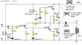
There are now several "minimalist" JLH'69 kits based on 2SC5200 output devices out there, in the online shopping world. It's odd that other semis like TIP35 or TIP3055 aren't offered, since they are likely closer to original types. Some assembled kits will probably never fly at full power, given the small offcut of heatsink supplied for both channels. The kits are very cheap and cheap is what sells best, even though there are no recommendations to use a smaller power supply to suit, rather than the original type which is guaranteed to overheat with the original design power supply of 27VDC.
Anyway, I was thinking of recommending that a hesitant friend of mine should just buy a cheap kit based on 2SC5200 for example and start assembling his own JLH amplifier. Now, following John's findings, there would seem to be some risk of "thermal runaway", especially in the hands of newbies. This makes me think twice about semis for class A. For my own interest, I've started my own mini-JLH kit project which came pre-assembled on two 50x50mm PCBs, each fitted with 2SC5198 power transistors. These are a TO3P case version of 2SC5200 and must have been really cheap. I dislike hot heatsinks and boxes so, following earlier discussion, my project is to see just how cool I can keep the amplifiers plus a basic preamp in the one small box, while still having a max. undistorted power output up near 10W/8R.
Anyway, I was thinking of recommending that a hesitant friend of mine should just buy a cheap kit based on 2SC5200 for example and start assembling his own JLH amplifier. Now, following John's findings, there would seem to be some risk of "thermal runaway", especially in the hands of newbies. This makes me think twice about semis for class A. For my own interest, I've started my own mini-JLH kit project which came pre-assembled on two 50x50mm PCBs, each fitted with 2SC5198 power transistors. These are a TO3P case version of 2SC5200 and must have been really cheap. I dislike hot heatsinks and boxes so, following earlier discussion, my project is to see just how cool I can keep the amplifiers plus a basic preamp in the one small box, while still having a max. undistorted power output up near 10W/8R.
Last edited:
This is becoming more confused as we look at the short history of the product(s). As far as I have read today, both types are fabbed in Japan but one is assembled in Japan, the other in China yet both products are labelled "JAPAN" as the last place of significant manufacturing process.. I'm not sure which type is which now. Then there are TO3P variants like 2SC5200N, S1,E,S which presumably are graded for gain or some other significant variable. The deeper you dig into these popular semis, the more confusing it gets.... and for those of you contemplating using TTC5200's (genuine, I hope) there is better news. The datasheet shows typical gains of (an approximate) 120 to 180 over a 75C change, which is at least an improvement over the 2SC5200. According to datasheets I have.
e.g. https://www.mouser.com/datasheet/2/408/2SC5200N_datasheet_en_20150512-1799632.pdf
I have some Toshiba TTC5200 transistors here, and they are printed with Japan on the face - I am assuming they are genuine as they were purchased from Digikey last year. Will be using these for a JLH build. The trouble is in this day and age - who knows what factory located in what country are devices assembled from the big Semi makers!
Thermal performance - when I came to switch off last night, after about 4 hours, the heatsink had apparently stablised at 49.5C and the current at 1.39A. Room temperature had cooled too, by about half a degree, so that suggests thermal equilibrium had been reached.
That raises a couple of questions. The heatsink at 0.7K/W was, according to my calculation earlier, right on the margin of stability. So it may in fact be stable. The transistor gain variation with temperature may not be quite as high as I estimated (you can read the graph on the datasheet Ian posted and see if you think 170C might be a better interpretation than 180! I erred on the cautious side, to be, errr, cautious.)
Nevertheless some form of temp control seems important as the circuit will change with room temperature variation let alone whether the heatsink is big enough or not.
Rather than rebuild the unit onto a smaller heatsink I may, in the interests of science, as they say, block off some of the fins to see if I can emulate a 1C/W unit.
If anyone has a kit which claims to run at 27V /1.2A and provide 10W 8 ohms would you be able to measure the heatsink (if supplied) thermal resistance?
(The principle is simple. Put a known power into the heatsink and measure the temperature rise compared with room temperature. Practically, you would mount a transistor on it with its insulator and run a constant current through it set by a moderately large emitter resistor and fixed base voltage. That might mean having to use a zener diode (supported by a transistor to increase power handling, perhaps) or two power supplies in series (the other running the collector). And having a thermometer or preferably thermocouple on the heatsink with adequate thermal contact. Something like 5 or 10W (depending on how big) should be enough depending on how accurately you can measure the power in and temperature.
You'd likely have to regulate a simple raw DC supply to wind up with approximately 27VDC nowadays. The rationalised stock range of transformer voltages (i.e. 12,15,18, 25, 35VAC. etc.) now means there will be a wide gap from about 25VDC to 35VDC. Of course, one could spend up on a custom wound transformer or a cheap bench power supply would quickly solve that problem too but not every audio DIY sees a need and budgets for decent instruments and bench gear 
Yes, the voltages do seem to be standardised, but in the UK we can get 30V units. Though they are double the price they were not so long ago.
It would be tempting to use a 25V transformer and large capacitors perhaps with another RC filter to minimise the PSU complexity.
Though I would recommend a stabilised PSU because the centre rail is referenced to the PSU rail. Filtering it will minimise hum etc but not eliminate slower variations.
I agree that 27V is somewhat uncommon and probably needs a stabilised PSU to get that, but the JLH capacitor multiplier is tweakable though as I've mentioned before I don't think that is an ideal solution.
After blocking half of the fins on the heatsink of my C5200 JLH implementation, the heatsink temperature stabilised at 60C rather than 49.5. But I am pleased to say it did not provoke thermal runaway.
From my initial calculations the effective heatsink thermal resistance was 0.95K/W.
So why no thermal runaway?
The good news is that of course, if you plan the thermal resistance of the heatsink to dissipate the expected power while keeping the transistors below or at their maximum temperature then it should work in a stable condition. So for example if my proposed circuit needs a 32V rail and 1.3A that is 42W of heat to get rid of. With an ambient temperature of (say) 40 degrees - and I make the assumption that some folks may have their heatsink facing a sunny window in summer, but also things are generally getting hotter - and the thermal resistance of the two transistors is 1.24/2 or 0.62 K/W, then a heatsink of 2K/W is the absolute smallest which can be used BUT it will reach a temperature of over 100C at an ambient of 20C, and it has no safety margin. That is not safe to be in the open and needs a cage or other surround to prevent contact.
The very important caveat is this: the quiescent current has to be set at the target value at the maximum ambient temperature expected. If the ambient is lower than the maximum allowed, the corollary is that the quiescent current will reduce, and peak power will not be available without some form of clipping.
To understand the thermal issues a little more I measured the Vbe immediately after switching on and again at the stable temperature. The datasheet is not very helpful with the Vbe:Ic graph (it should have been plotted with a logarithmic scale), but taking readings as best I could I obtained the two data points (1) that the change in Vbe from 25 to 100C is 132mV (approximately) and (2) that at 1.2A the change in Vbe with current is 45.2mV/A at 25C and 56.8mV/A at 100C.
From these numbers the temperature change of the junctions was 60C and since the heatsink change was 40C (taking room temperature as 20C) that puts the thermal resistance of junction to heatsink about 1C/W. I used silicone pads rather than mica, and had estimated 1.2 so this is about as close as the data would permit. The change in gain of the transistors from 1.1A to 1.39A gives a ratio of 1.26, which for a 60C rise is lower than the original figure of 1.8/75.
That is a partial explanation - the gain change with temperature is not as large as originally estimated.
The two take-away conclusions are (1) make sure the amplifier has stabilised before setting the nominal current, at your worst case allowed ambient, allowing another stabilisation time between adjustments if necessary, but you won't get full power from a cold start.
(2) the change in current with temperature is still unacceptable if you want the best efficiency from both a cold start and when warmed up; and if you want to allow operation in a wide range of ambient temperatures.
Therefore I would still say it needs a thermal control - so the next thing will be to implement the suggested control circuit and check.
But the story does not end here. I simulated the circuit with a 1uF capacitor load and 10kHz square wave. The good news is that, as expected, it is stable.
The bad news is that another problem I have raised in the past is, well, another problem. When the input signal is going negative the lower output transistor is turned on while the upper output transistor is turned off. The capacitor loading needs a substantial current to pull it down quickly, and the upper output transistor cuts off. The problem here is that for a short pulse the upper output transistor sees a massive reverse bias on its base. This would exceed specifications and needs to be addressed if a capacitive load (electrostatic speakers for example) is to be used.
I have raised this as an issue in the dim and distant past, but as most users will only be using the amplifier with inductive or effectively resistive loads (ordinary speakers and/or crossover networks etc) then this will not be a problem, but could have caused some units to self destruct if not considered. It will not be a problem either if the input signal frequency or amplitude does not cause the output stage to exceed the output current capability.
Perhaps this is one of the design "quirks" of the JLH that because the unit is operating in Class A with a fixed static current, that current is the maximum which can be output without clipping or slew rate limiting. That means any capacitor loading cannot be driven faster than the current permits. With a 1uF capacitor the slew rate is "only" 1.2MV/s which isn't enough for 20kHz at 10W/8 ohms. (I have to point out that the 1uF was in parallel with an 8 ohm load) . So - not an electrostatic driver!
Diode...Resistor 100 ohm (DoZ)massive reverse bias on its base.
Hello fellow DIYers. Recently my wife said I needed a hobby, and know I used to be into car audio thought I'd like to get back into it, but for the home. So she got me the JLH1969 with the 3055s from Ebay. Pretty cool. I bought a toroidal from Antek (20v x2 @5A per coil) and the recommended psu module for the amp from Ebay also. My question is after that 20vac gets changed to dc (20vac x 1.414= 28.3 or higher with no load) is this too high a voltage? Should I get an 18vac x 2? I don't want to ruin anything. Sorry for an absolute noob question but we all have to start somewhere.
Yes, obvious but no-one has said this before in a JLH as far as I know.Diode...Resistor 100 ohm (DoZ)
Question: where to put?
In series with the base? No- because it will have a high impedance and disconnect the transistor when turning off (not fast).
Add capacitor? - critical value so as not to exceed reverse bias but possible.
In parallel? No- because then the driver transistor shunts the current. Possibly blows the driver.
Actually with my series resistor in the base that would work. It allows the negative slew rate to be quick (I already tried this in sim) and the resistor limits the current. Perhaps that was the resistor you were thinking of?
Then you have the problem that the negative slew is faster than the positive (pulse of current in the driver, switches lower output device on rapidly.). So now the positive slew needs to be raised ...
when to stop modding?
Last edited:
I take it you have a meter? Using one coil you will get 28V plus an overhead due to the winding resistance set by the transformer designer. That is countered by the voltage drop across the bridge rectifier you need. If you have a single channel as you appear to, the ripple voltage will be 2 or 3V so to power the amp you need to run the amp at least at the ripple voltage below, so that means your amp would probably have to run at 23 or 24V, if the power supply capacitor is 5mF as JLH specified. With your higher current transformer (5A) a larger capacitor is possible and will reduce the ripple.cms1112..
Make sure you have the circuit diagram for the PSU and check the value of the main capacitor.
You might find that you don't have enough volts. JLH recommended a 30V transformer (45V rectified) but unfortunately putting your 2x20V in series will be too high. (Unless you run 15 ohm speakers).
A 20V transformer was recommended for 4 ohm loads, so if that is what you plan to use you should be OK.
Diode parallel to junction (reverse).In parallel?
Zener.
Attachments
Last edited:
Thank you John. I don't have schematics or diagrams for the psu. But the pics are what were ordered. And my speakers are Dayton B652-AIRs. 6ohms for the drivers. I'm guessing that's ok.I take it you have a meter? Using one coil you will get 28V plus an overhead due to the winding resistance set by the transformer designer. That is countered by the voltage drop across the bridge rectifier you need. If you have a single channel as you appear to, the ripple voltage will be 2 or 3V so to power the amp you need to run the amp at least at the ripple voltage below, so that means your amp would probably have to run at 23 or 24V, if the power supply capacitor is 5mF as JLH specified. With your higher current transformer (5A) a larger capacitor is possible and will reduce the ripple.
Make sure you have the circuit diagram for the PSU and check the value of the main capacitor.
You might find that you don't have enough volts. JLH recommended a 30V transformer (45V rectified) but unfortunately putting your 2x20V in series will be too high. (Unless you run 15 ohm speakers).
A 20V transformer was recommended for 4 ohm loads, so if that is what you plan to use you should be OK.
Attachments


- Home
- Amplifiers
- Solid State
- JLH 10 Watt class A amplifier